(3) · also written as a run, 3a xxx 3n
Fluid-Medium
Also written magnetic fluid-medium · permanent magnetic fluid-medium · permanently magnetized fluid-medium · magnetized fluid-medium · moving fluid-medium · permanently magnetized material · magnetic material · material and 7 more
Where it is first named
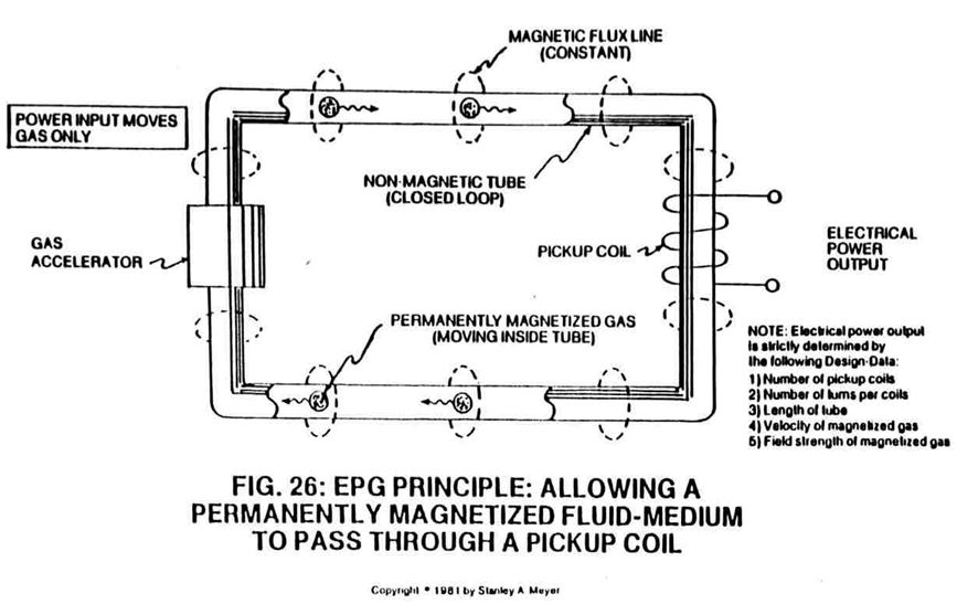
Said Particle Accelerator Assembly (10) causes and propels a permanent magnetic fluid-medium (3 of Figure 26) (liquid slurry or gases) to move toward, through, and beyond said pickup coils (2) for recycling, as illustrated in Figure 26.
How it is written
- (3) 18×
- (3a xxx 3n) 11×
- (3a) 1×
- (3 of Figure 26) 1× with Figure (26) EPG Principle
3a xxx 3n is Meyer's shorthand for a run of the same thing: 3a is the first, 3n the last, and the x's stand for however many lie between. Every stage of the run is this one numeral.
Drawings 7
-
The figure it sits on · ELECTRICAL PARTICLE GENERATOR
-
Pulse-frequency electrical output (23 of Figure 30 as to Figure 27) is strictly determined by the pulse-rate of said orientation coils (12/13). · ELECTRICAL PARTICLE GENERATOR
-
When EMF field (31) is formed, said pulsating magnetic field (29) forming concentric ring (29) is turned off (switched off). · ELECTRICAL PARTICLE GENERATOR
-
The figure it sits on · ELECTRICAL PARTICLE GENERATOR
-
The figure it sits on · ELECTRICAL PARTICLE GENERATOR
-
The figure it sits on · ELECTRICAL PARTICLE GENERATOR
-
The figure it sits on · ELECTRICAL PARTICLE GENERATOR
Where it is named · 31
ELECTRICAL PARTICLE GENERATOR 31×
-
magnetic fluid-medium (3)
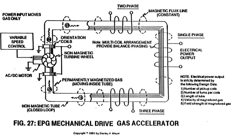
A Mechanical Accelerator Drive Assembly (20 of Figure 27) utilizes a non-magnetic turbine wheel (21) to physically move said magnetic fluid-medium (3) inside said tubular pathway (1).
-
fluid-medium (3)
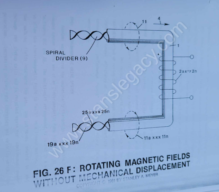
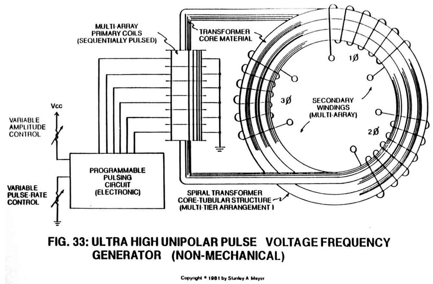
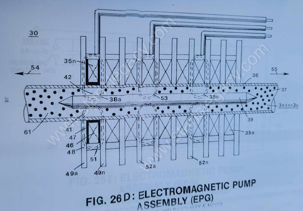
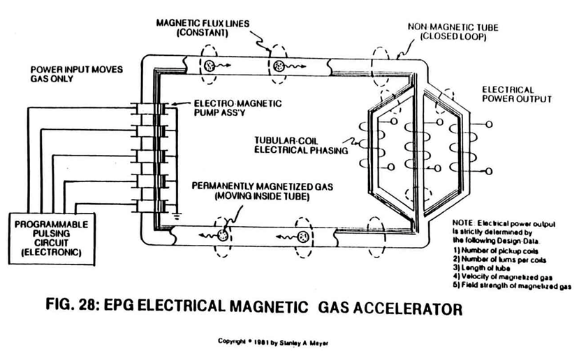
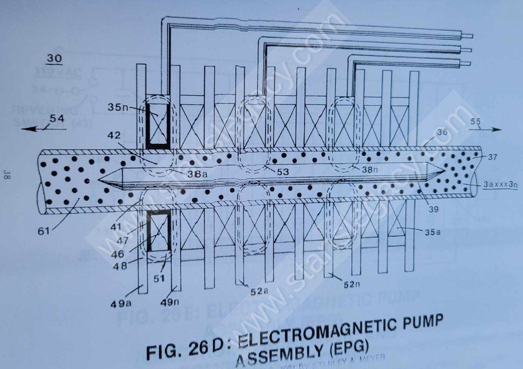
Electromagnetic Pump Assembly (30 of Figure 28 as to Figure 33) moves said fluid-medium (3) by way of electromagnetic deflection, see Figure 26F.
-
permanently magnetized material (3)
Fill said closed loop tubular pathway (1) as to (8) with a permanently magnetized material (3), as illustrated in Figures 26, 27, 29, and 30.
-
permanently magnetized material (3)
Said permanently magnetized material (3) can either be in a liquid slurry and/or gas form.
-
permanently magnetized material (3)
Once said tubular pathway (1) as to (8) is completely filled with said permanently magnetized material (3), said pickup coil-array (2a xxx 2n) is electrically energized to produce an electromagnetic field that completely surrounds said tubular pathway (8) of Figure 33, exposing said magnetic material (3) to said electromagnetic field... …
-
magnetic material (3)
… (3), said pickup coil-array (2a xxx 2n) is electrically energized to produce an electromagnetic field that completely surrounds said tubular pathway (8) of Figure 33, exposing said magnetic material (3) to said electromagnetic field... causing said material (3) to become permanently magnetized...forming a longitudinal field (4) of Figure 26 emitting from said tubular pathway (1).
-
material (3)
… causing said material (3) to become permanently magnetized...forming a longitudinal field (4) of Figure 26 emitting from said tubular pathway (1).
-
permanently magnetized particles (3a xxx 3n)
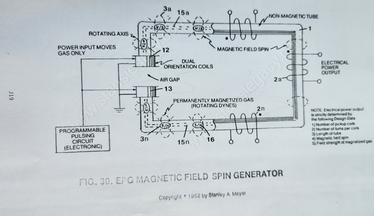
First, when electrically energized, said dual-coils (12/13) stabilize said magnetic field (4/11) since said turbine wheel (21 of assembly 20) disrupts the electromagnetic field alignment (15a xxx 15n) (electromagnetic attraction force) between said permanently magnetized particles (3a xxx 3n) moving inside non-magnetic tubular pathway (1 as to 8), see Figure 27 as to Figure 30.
-
particles (3a xxx 3n)
Re-energizing said coils (12/13) causes said particles (3a xxx 3n) to go into alignment once again... reforming magnetic field (4/11).
-
particle (3)
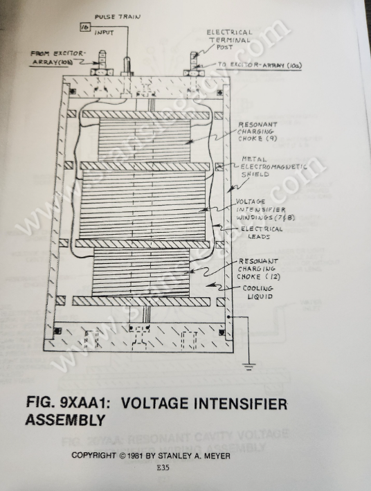
Variable Pulse Voltage Frequency Generator (14 of Figure 27) (Figure 9XB as to Figure 9XAA) is used to trigger or energize said pulsing coils at the same time (12/13) during particle (3) deflection.
-
particles (3a xxx 3n)
Transformer interaction (magnetic field coupling) between said Orientation Coils (12/13) and said pickup coils (2a xxx 2n) can "NOT" occur since said particles (3a xxx 3n) are permanently magnetized.
-
particle (3a xxx 3n)
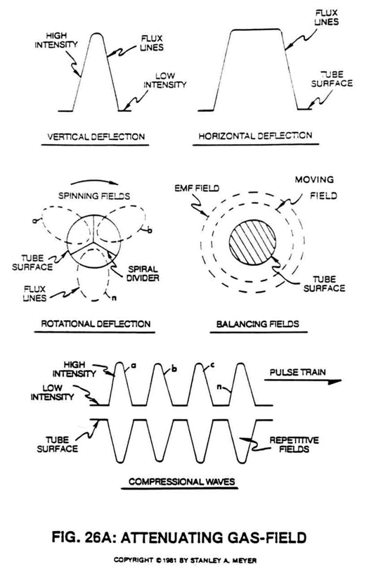
To move more magnetic flux lines through said pickup coil-array (2a xxx 2n) while keeping said particle (3a xxx 3n) velocity constant, said Spiral Divider (9) of Figure 26F is now subdivided into many pathway channels (19a xxx 19n), as illustrated in Figure 26A sub-titled "Rotational Deflection."
-
magnetized fluid-medium (3a xxx 3n)
To speed up said magnetic field spin (11a xxx 11n), simply increase the velocity of said magnetized fluid-medium (3a xxx 3n) traveling through said pathways (19a xxx 19n)... or vice versa.
-
permanent magnetic fluid-medium (3a)
The velocity or movement of said permanent magnetic fluid-medium (3a) inside tubular pathway (1) (magnetic field movement per second in a linear direction).
-
fluid-medium (3)
The magnetic field strength (number of magnetic flux-lines per unit volume of said magnetic fluid-medium (3)).
-
magnetic fluid-medium (3)
The pulse-rate frequency of said orientational coils (12/13) to spin or rotate said dyne-axis of said magnetic fluid-medium (3) to oscillate said permanent magnetic field (11a xxx 11n).
-
magnetic fluid-medium (3)
Power input is required to move said magnetic fluid-medium (3) through said closed-loop tubular pathway (1).
-
fluid-medium (3)
Power input is also required to rotate said dyne-axis of said magnetized fluid-medium (3).
-
permanently magnetized fluid-medium (3)
The basic purpose of said power input is to physically attenuate said permanently magnetized fluid-medium (3)... which in turn oscillates a permanent magnetic field (4/11).
-
fluid-medium (3a xxx 3n)
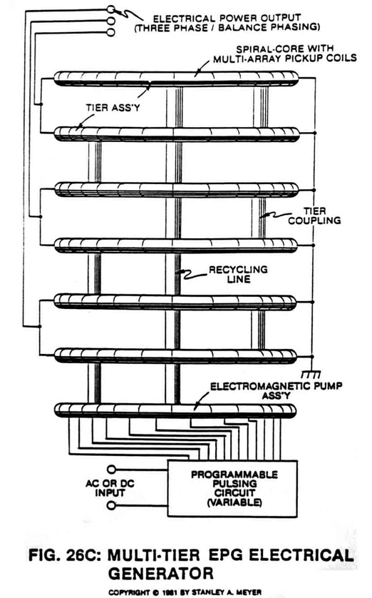
To bypass and overcome the mechanical limitation of said Turbine Pump Assembly (20 of Figure 27), the Electromagnetic Pump Assembly (30 as to Figure 26F) in relationship to Figure 26C is utilized to propel said fluid-medium (3a xxx 3n) of Figure 26 as to Figure 26C.
-
magnetic field medium (3a xxx 3n)
The coil-array (35a xxx 35n) of Figure 26C, besides being the stator, the magnetic field medium (3a xxx 3n) is displaced along a movable/non-movable electromagnetic tubular surface (of Figure 26C) which, in reference to Figure 28) acts as a bearing surface (since said surface (35a xxx 35n) is fixed).
-
moving fluid-medium (3a xxx 3n)
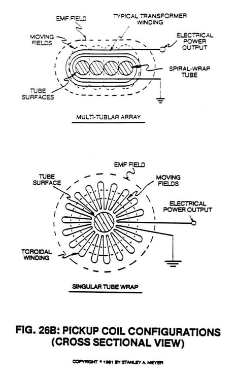
The linear motion of said moving fluid-medium (3a xxx 3n) through the stator assembly (30) is shown in Figure 26A to Figure 33F of Figure 26B which is essentially a series of coils as stator assembly (30) which is essentially a series of coils as stator assembly (35a xxx 35n) of Figure 26C as to Figure 26 and Figure 33.
-
fluid-medium (3)
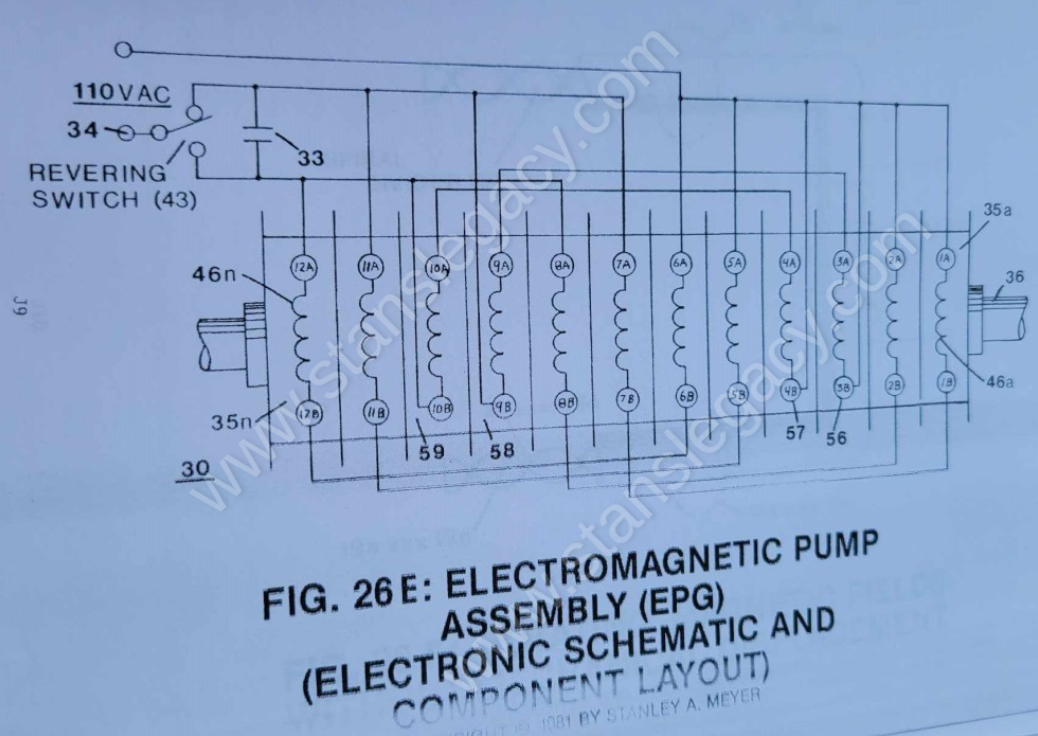
A simple mechanical switching (43 of Figure 26E) reverses the sweep of fields (38a xxx 38n) and moves the direction of fluid-medium (3) travel.
-
fluid-mass (3)
Once the magnetized fluid-mass (3) is aligned by said magnetic deflection (pulsing) attraction forces (53 of Figure 26C) and "locks-onto" said permanently magnetized fluid-medium (3a xxx 3n).
-
fluid-medium (3a xxx 3n)
Once the magnetized fluid-mass (3) is aligned by said magnetic deflection (pulsing) attraction forces (53 of Figure 26C) and "locks-onto" said permanently magnetized fluid-medium (3a xxx 3n).
-
fluid-mass (3)
Wiring of said coils (46a xxx 46n) in proper sequence (see wiring schematic Figure 26E) with said capacitor (33) produces a sweeping magnetic wave (38a xxx 38n) across said fluid-mass (3), thus allowing said fluid-mass movement (54).