Figure (26F)
Figure (26F)
How it is written
- (26F) 8× with (26F)
- (30 as to Figure 26F) 1×
Drawings 1
-
Beside the passage · ELECTRICAL PARTICLE GENERATOR
On this figure 13
- 1 Tubular Pathway
- 2 Coil-Array
- 3 Fluid-Medium
- 4 Magnetic Field
- 8 Non-Magnetic Tubular Pathway
- 9 Spiral Divider
- 11 Magnetic Field
- 19 Pathway Channels
- 20 Power Drive System
- 25 —
- 30 Stator Assembly
- 31 EMF field
- 48 Magnetic "Shunt" Assembly
Where it is named · 9
ELECTRICAL PARTICLE GENERATOR 9×
-
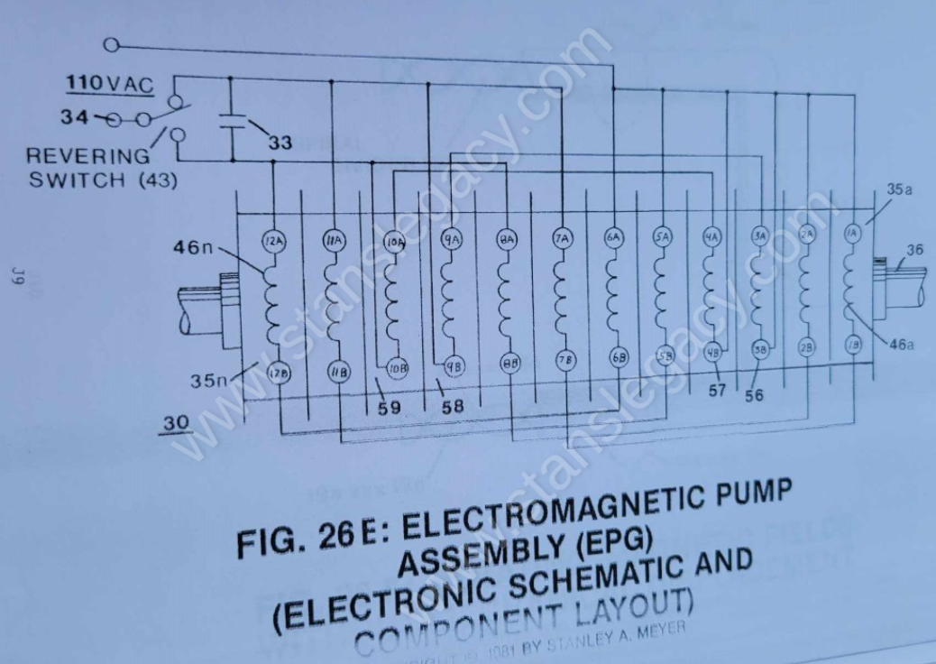
Electromagnetic Pump Assembly (30 of Figure 28 as to Figure 33) moves said fluid-medium (3) by way of electromagnetic deflection, see Figure 26F.
-
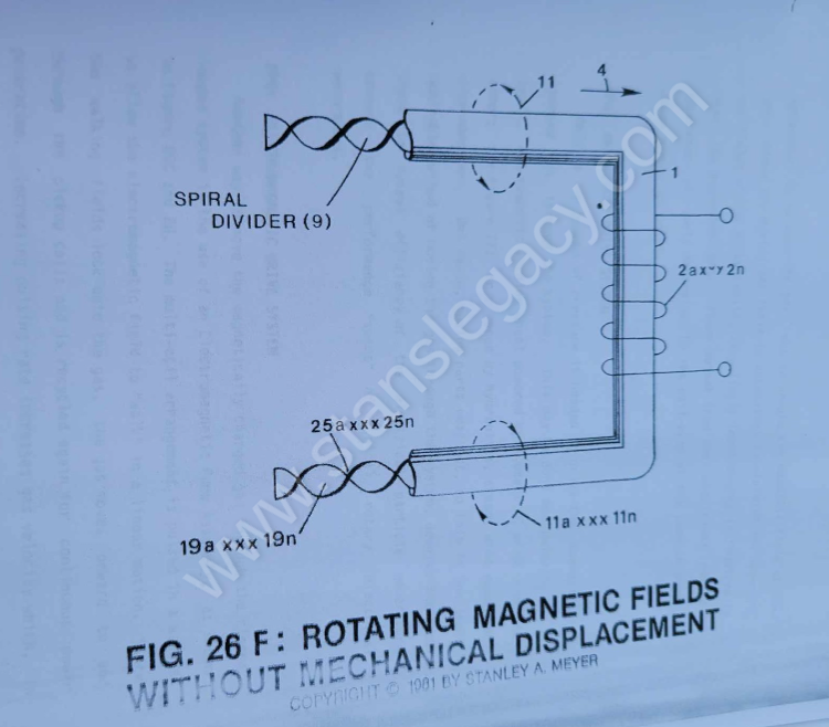
To spin or rotate said magnetic field (4) as to (11 of Figure 26) on its longitudinal axis while moving in a linear direction (4 of Figure 26, 27, and 28) as described above, a Spiral Divider (9) of Figure 26F is now inserted into said tubular pathway (1) leading away from and connecting said Power Drive System (20/30), said Spiral Divider (9) passing through said pickup coil-array (2a xxx 2n), said Spiral …
-
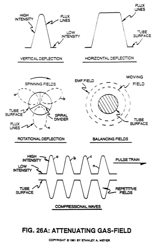
To move more magnetic flux lines through said pickup coil-array (2a xxx 2n) while keeping said particle (3a xxx 3n) velocity constant, said Spiral Divider (9) of Figure 26F is now subdivided into many pathway channels (19a xxx 19n), as illustrated in Figure 26A sub-titled "Rotational Deflection."
-
By increasing the number of turns (twist configurations) (25a xxx 25n of Figure 26F) per linear measurement of said spiral-divider cluster (19a xxx 19n) also increases said magnetic spin (4/11) still further once said fluid-velocity (4) is reached.
-
To help minimize opposition to the movement of said magnetic fluid-medium during power on-stage, said pickup coil array (2a xxx 2n) of Figure 33 as to Figure 26F is placed and aligned end-to-end around said pathway (8a xxx 8n) for the purpose of coupling and forming a single and continuous magnetic field (31) or any type of electromagnetic field emanating from said pickup coil-array (during duty loading) is wrapped and positioned around said pickup coil-array (2a xxx 2n)... …
-
To bypass and overcome the mechanical limitation of said Turbine Pump Assembly (20 of Figure 27), the Electromagnetic Pump Assembly (30 as to Figure 26F) in relationship to Figure 26C is utilized to propel said fluid-medium (3a xxx 3n) of Figure 26 as to Figure 26C.
-
To bypass and overcome the mechanical limitation of said Turbine Pump Assembly (20 of Figure 27), the Electromagnetic Pump Assembly (30 as to Figure 26F) in relationship to Figure 26C is utilized to propel said fluid-medium (3a xxx 3n) of Figure 26 as to Figure 26C.
-
Said Magnetic "Shunt" Assembly (48) is composed of electrical steel that will push the magnetic field toward said moving permanently magnetized mass, as illustrated in Figure 26F.