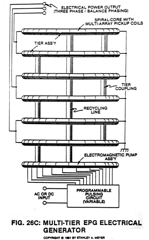
Figure (26C)
Multi-tier EPG Electrical Generator Copyright
How it is written
- (26C) 8×
- (53 of Figure 26C) 1×
- (of Figure 26C) 1×
Drawings 2
-
Captioned as this figure · ELECTRICAL PARTICLE GENERATOR
-
Beside the passage · ELECTRICAL PARTICLE GENERATOR
On this figure 5
- 3 Fluid-Medium
- 8 Non-Magnetic Tubular Pathway
- 11 Magnetic Field
- 30 Stator Assembly
- 35 Stator Assembly
Where it is named · 10
ELECTRICAL PARTICLE GENERATOR 10×
-
The number of "shunting" magnetic fields (11a xxx 11n) times (x) the number of spiral pathways (8a xxx 8n) determine the magnetic field strength of said EPG system of Figure 26C.
-
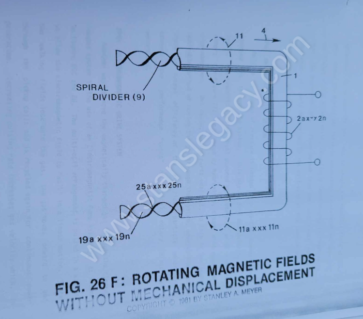
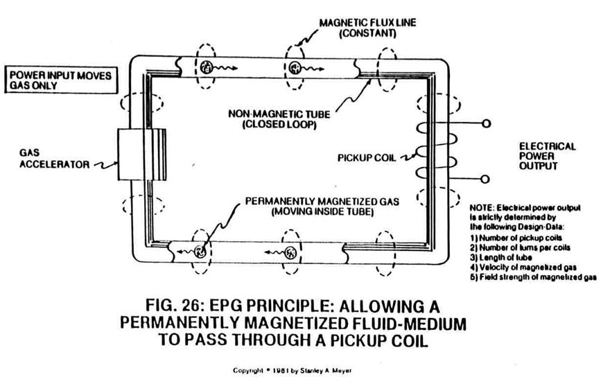
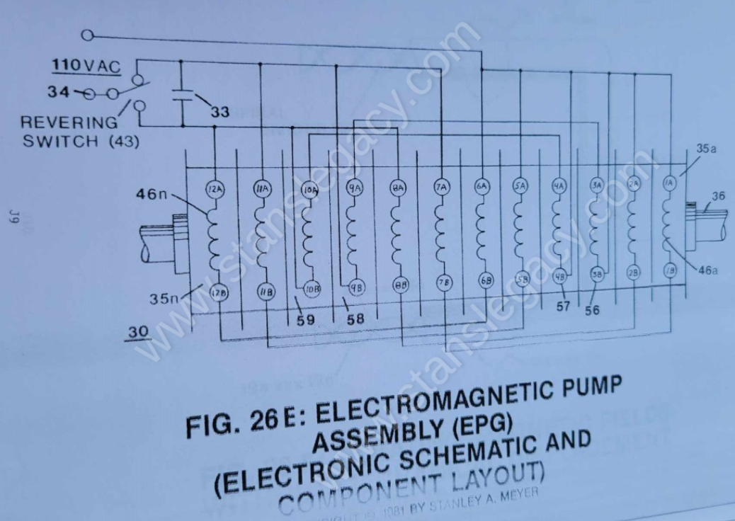
To bypass and overcome the mechanical limitation of said Turbine Pump Assembly (20 of Figure 27), the Electromagnetic Pump Assembly (30 as to Figure 26F) in relationship to Figure 26C is utilized to propel said fluid-medium (3a xxx 3n) of Figure 26 as to Figure 26C.
-
To bypass and overcome the mechanical limitation of said Turbine Pump Assembly (20 of Figure 27), the Electromagnetic Pump Assembly (30 as to Figure 26F) in relationship to Figure 26C is utilized to propel said fluid-medium (3a xxx 3n) of Figure 26 as to Figure 26C.
-
The coil-array (35a xxx 35n) of Figure 26C, besides being the stator, the magnetic field medium (3a xxx 3n) is displaced along a movable/non-movable electromagnetic tubular surface (of Figure 26C) which, in reference to Figure 28) acts as a bearing surface (since said surface (35a xxx 35n) is fixed).
-
The coil-array (35a xxx 35n) of Figure 26C, besides being the stator, the magnetic field medium (3a xxx 3n) is displaced along a movable/non-movable electromagnetic tubular surface (of Figure 26C) which, in reference to Figure 28) acts as a bearing surface (since said surface (35a xxx 35n) is fixed).
-
The coil-array (35a xxx 35n) of Figure 26C, besides being the stator, the magnetic field medium (3a xxx 3n) is displaced along a movable/non-movable electromagnetic tubular surface (of Figure 26C) which, in reference to Figure 28) acts as a bearing surface (since said surface (35a xxx 35n) is fixed).
-
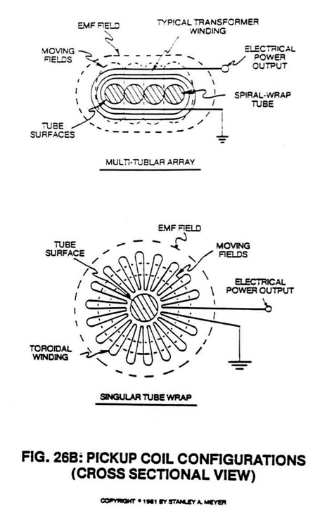
The linear motion of said moving fluid-medium (3a xxx 3n) through the stator assembly (30) is shown in Figure 26A to Figure 33F of Figure 26B which is essentially a series of coils as stator assembly (30) which is essentially a series of coils as stator assembly (35a xxx 35n) of Figure 26C as to Figure 26 and Figure 33.
-
Once the magnetized fluid-mass (3) is aligned by said magnetic deflection (pulsing) attraction forces (53 of Figure 26C) and "locks-onto" said permanently magnetized fluid-medium (3a xxx 3n).
-
Once the magnetized fluid-mass (3) is aligned by said magnetic deflection (pulsing) attraction forces (53 of Figure 26C) and "locks-onto" said permanently magnetized fluid-medium (3a xxx 3n).