(11) · also written as a run, 11a xxx 11n
Magnetic Field
Also written permanent magnetic field · collapsing magnetic field · magnetic field spin · multi-rotational fields · magnetic flow circuits · Linear-Spin movement · magnetic flux lines · magnetic circuits and 5 more
Where it is first named
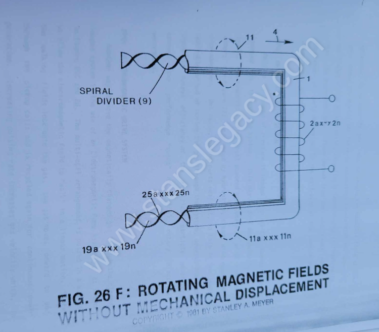
To spin or rotate said magnetic field (4) as to (11 of Figure 26) on its longitudinal axis while moving in a linear direction (4 of Figure 26, 27, and 28) as described above, a Spiral Divider (9) of Figure 26F is now inserted into said tubular pathway (1) leading a …
How it is written
- (11a xxx 11n) 10×
- (4/11) 10×
- (11) 4×
- (11 of Figure 26) 1× with Figure (26) EPG Principle
- (4/11 as to 17/18) 1×
11a xxx 11n is Meyer's shorthand for a run of the same thing: 11a is the first, 11n the last, and the x's stand for however many lie between. Every stage of the run is this one numeral.
Drawings 7
-
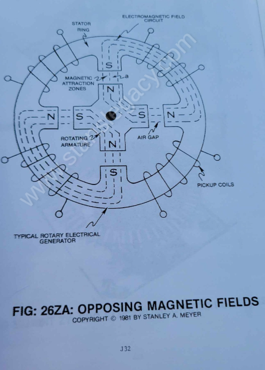
In both cases, said magnetic field spin (11a xxx 11n) is not subject to the rotational/mechanical limitation of said Rotary Electrical Generator of Figure 26ZA. · ELECTRICAL PARTICLE GENERATOR
-
The figure it sits on · ELECTRICAL PARTICLE GENERATOR
-
Pulse-frequency electrical output (23 of Figure 30 as to Figure 27) is strictly determined by the pulse-rate of said orientation coils (12/13). · ELECTRICAL PARTICLE GENERATOR
-
When EMF field (31) is formed, said pulsating magnetic field (29) forming concentric ring (29) is turned off (switched off). · ELECTRICAL PARTICLE GENERATOR
-
The figure it sits on · ELECTRICAL PARTICLE GENERATOR
-
The figure it sits on · ELECTRICAL PARTICLE GENERATOR
-
The figure it sits on · ELECTRICAL PARTICLE GENERATOR
Where it is named · 26
ELECTRICAL PARTICLE GENERATOR 26×
-
To spin or rotate said magnetic field (4) as to (11 of Figure 26) on its longitudinal axis while moving in a linear direction (4 of Figure 26, 27, and 28) as described above, a Spiral Divider (9) of Figure 26F is now inserted into said tubular pathway (1) leading a …
-
magnetic field (4/11)
The linear-spin movement of said magnetic field (4/11) now duplicates the magnetic field spin of Figure 26ZA without the opposing magnetic field problem (caused by said "Air Gap") associated with standard rotary electrical generators, see "Pre-History to Development" again.
-
magnetic field (4/11)
whereas, the EPG System now moves said magnetic field (4/11) in two directions simultaneously:
-
(11) axial or spin rotation.
-
rotational field (11)
To pulsate or vary said rotational field (11) moving in a linear direction (4), Dual-Orientational coils (12/13 of Figure 27) are now inserted into said tubular pathway on opposite side of Electromechanical Drive System (20), away from said pickup coil-array (2a xxx 2n), as illustrated in Figure (27) as to Figure 30.
-
magnetic field (4/11)
First, when electrically energized, said dual-coils (12/13) stabilize said magnetic field (4/11) since said turbine wheel (21 of assembly 20) disrupts the electromagnetic field alignment (15a xxx 15n) (electromagnetic attraction force) between said permanently magnetized particles (3a xxx 3n) moving inside non-magnetic tubular pathway (1 as to 8), see Figure 27 as to Figure 30.
-
moving field (4/11)
Secondly, said moving field (4/11) is terminated when said dual-coil assembly (12/13) is de-energized... allowing said particles (15a xxx 15n) to go into a state of reformation of said magnetic field sequence.
-
magnetic field (4/11)
Re-energizing said coils (12/13) causes said particles (3a xxx 3n) to go into alignment once again... reforming magnetic field (4/11).
-
magnetic field (4/11)
Pulsing said Orientation-coils (12/13) quickly causes a vertical deflection (17a xxx 17n of Figure 26A) of said magnetic field (4/11).
-
magnetic field (4/11)
Pulsing said Orientation-coils slowly causes a horizontal deflection (18a xxx 18n of Figure 26A) of said magnetic field (4/11).
-
magnetic field (4/11 as to 17/18)
The magnetic pulsing process simply spins the dyne-axis of said particles (3a xxx 3n) to oscillate and attenuate a permanent magnetic field (4/11 as to 17/18), as illustrated in Figure 30 as to Figure 26 through Figure 33.
-
Spinning (11)
Spinning (11) said pulsating magnetic field (17/18) in a linear (4) direction... simultaneously.
-
magnetic field (11a xxx 11n)
The multi-channel spiral divider (19a xxx 19n) is composed of any type of material (such as electrical steel M27) that will "NOT" become permanently magnetized (when exposed to said moving magnetic field (4)) when "shunting" said magnetic field (11a xxx 11n), as shown in Figure 26A sub-titled "Rotational Deflection."
-
magnetic flow circuits (11a xxx 11n)
Since each spiral channel pathway (19) performs the same function as said pathway (1), many magnetic flow circuits (11a xxx 11n) are formed as to the number of said pathway channels (19a xxx 19n).
-
magnetic flux lines (11a xxx 11n)
To increase said magnetic flux lines (11a xxx 11n) still further, said pathway (1) is now spiraled (8 of Figure 33) (in spaced relationship to each other) inside said pickup coil-array (2a xxx 2n), as illustrated in Figure 33 as to cross-sectional drawing titled "Multi-tubular array"of Figure 28A.
-
The number of "shunting" magnetic fields (11a xxx 11n) times (x) the number of spiral pathways (8a xxx 8n) determine the magnetic field strength of said EPG system of Figure 26C.
-
magnetic field spin (11a xxx 11n)
To speed up said magnetic field spin (11a xxx 11n), simply increase the velocity of said magnetized fluid-medium (3a xxx 3n) traveling through said pathways (19a xxx 19n)... or vice versa.
-
magnetic spin (4/11)
By increasing the number of turns (twist configurations) (25a xxx 25n of Figure 26F) per linear measurement of said spiral-divider cluster (19a xxx 19n) also increases said magnetic spin (4/11) still further once said fluid-velocity (4) is reached.
-
magnetic field spin (11a xxx 11n)
In both cases, said magnetic field spin (11a xxx 11n) is not subject to the rotational/mechanical limitation of said Rotary Electrical Generator of Figure 26ZA.
-
magnetic circuits (11a xxx 11n)
The number of pathway-channels (19a xxx 19n) per spiral-divider (9) forming magnetic circuits (11a xxx 11n) per spiral-divider (9) spinning in a linear direction per 360 degrees (the number of magnetic fields formed per second).
-
multi-fields (11a xxx 11n)
The number of turns or twist per (25a xxx 25n) unit length of said spiral divider (9) inserted into said tubular pathway (1), the number of magnetic fields spins of said multi-fields (11a xxx 11n) per second of linear-travel.
-
multi-rotational fields (11a xxx 11n)
The number of tubular-legs (8a xxx 8n) spiraled inside said pickup coil-array (2a xxx 2n). The number of multi-rotational fields (11a xxx 11n) formed per turns of tubular legs (8a xxx 8n).
-
permanent magnetic field (11a xxx 11n)
The pulse-rate frequency of said orientational coils (12/13) to spin or rotate said dyne-axis of said magnetic fluid-medium (3) to oscillate said permanent magnetic field (11a xxx 11n).
-
permanent magnetic field (4/11)
The basic purpose of said power input is to physically attenuate said permanently magnetized fluid-medium (3)... which in turn oscillates a permanent magnetic field (4/11).
-
collapsing magnetic field (4/11)
To obtain maximum operational efficiency of said Stator assembly (30), said magnetic keeper-bar (39) also acts as a magnetic field spoiler by disrupting particle alignment (15a xxx 15n of Figure 30)... collapsing magnetic field (4/11) prior to particle entrance into said Stator Assembly (30).