(1) · also written as a run, 1a xxx 1n
Tubular Pathway
Also written pathway · non-magnetic tubular pathway · closed loop tubular pathway · closed-loop tubular pathway · close-loop tubular pathway · non-magnetic tube · closed loop tube · tube and 2 more
Where it is first named
Said tubular pathway (1) can be extended into a spiral configuration (8) of Figure 33.
How it is written
- (1) 19×
- (1 as to 8) 1×
- (1a xxx 1n) 1×
1a xxx 1n is Meyer's shorthand for a run of the same thing: 1a is the first, 1n the last, and the x's stand for however many lie between. Every stage of the run is this one numeral.
Drawings 4
-
The figure it sits on · ELECTRICAL PARTICLE GENERATOR
-
When EMF field (31) is formed, said pulsating magnetic field (29) forming concentric ring (29) is turned off (switched off). · ELECTRICAL PARTICLE GENERATOR
-
The figure it sits on · ELECTRICAL PARTICLE GENERATOR
-
The figure it sits on · ELECTRICAL PARTICLE GENERATOR
Where it is named · 21
ELECTRICAL PARTICLE GENERATOR 21×
-
tubular pathway (1)
Said tubular pathway (1) can be extended into a spiral configuration (8) of Figure 33.
-
non-magnetic tube (1)
Wrap a wire-coil (2) and/or coil-array (2a xxx 2n) around one end of said non-magnetic tube (1) to comply with Maxwell/Faraday Laws of Inductance.
-
closed loop tube (1)
Insert into and affixed a Particle Accelerator Assembly (10) to said closed loop tube (1) as to (8), locating said Particle Accelerator Assembly on opposite end of tube (1) away from said pickup windings (2 xxx 2n), as shown in Figure 26.
-
tube (1)
Insert into and affixed a Particle Accelerator Assembly (10) to said closed loop tube (1) as to (8), locating said Particle Accelerator Assembly on opposite end of tube (1) away from said pickup windings (2 xxx 2n), as shown in Figure 26.
-
tubular pathway (1)
A Mechanical Accelerator Drive Assembly (20 of Figure 27) utilizes a non-magnetic turbine wheel (21) to physically move said magnetic fluid-medium (3) inside said tubular pathway (1).
-
closed loop tubular pathway (1)
Fill said closed loop tubular pathway (1) as to (8) with a permanently magnetized material (3), as illustrated in Figures 26, 27, 29, and 30.
-
tubular pathway (1)
Once said tubular pathway (1) as to (8) is completely filled with said permanently magnetized material (3), said pickup coil-array (2a xxx 2n) is electrically energized to produce an electromagnetic field that completely surrounds said tubular pathway (8) of Figure 33, exposing said magnetic material (3) to said electromagnetic field... …
-
tubular pathway (1)
… causing said material (3) to become permanently magnetized...forming a longitudinal field (4) of Figure 26 emitting from said tubular pathway (1).
-
tubular pathway (1)
… of Figure 26) on its longitudinal axis while moving in a linear direction (4 of Figure 26, 27, and 28) as described above, a Spiral Divider (9) of Figure 26F is now inserted into said tubular pathway (1) leading away from and connecting said Power Drive System (20/30), said Spiral Divider (9) passing through said pickup coil-array (2a xxx 2n), said Spiral Divider (9) terminating at and not passing th …
-
non-magnetic tubular pathway (1 as to 8)
First, when electrically energized, said dual-coils (12/13) stabilize said magnetic field (4/11) since said turbine wheel (21 of assembly 20) disrupts the electromagnetic field alignment (15a xxx 15n) (electromagnetic attraction force) between said permanently magnetized particles (3a xxx 3n) moving inside non-magnetic tubular pathway (1 as to 8), see Figure 27 as to Figure 30.
-
pathway (1)
Since each spiral channel pathway (19) performs the same function as said pathway (1), many magnetic flow circuits (11a xxx 11n) are formed as to the number of said pathway channels (19a xxx 19n).
-
pathway (1)
To increase said magnetic flux lines (11a xxx 11n) still further, said pathway (1) is now spiraled (8 of Figure 33) (in spaced relationship to each other) inside said pickup coil-array (2a xxx 2n), as illustrated in Figure 33 as to cross-sectional drawing titled "Multi-tubular array"of Figure 28A.
-
close-loop tubular pathway (1)
--- Balance-Phasing (equal magnetic field strength between said pickup coil-array 2a xxx 2n) is automatic since particle velocity (4) remains constant while passing through said close-loop tubular pathway (1).
-
tubular pathway (1)
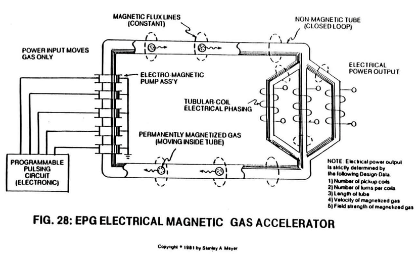
Pickup coil-array phasing (26a xxx 26n) also occurs when splitting said tubular pathway (1) into parallel legs (1a xxx 1n), as shown in Figure 28.
-
parallel legs (1a xxx 1n)
Pickup coil-array phasing (26a xxx 26n) also occurs when splitting said tubular pathway (1) into parallel legs (1a xxx 1n), as shown in Figure 28.
-
tubular pathway (1)
The velocity or movement of said permanent magnetic fluid-medium (3a) inside tubular pathway (1) (magnetic field movement per second in a linear direction).
-
tubular pathway (1)
The number of turns or twist per (25a xxx 25n) unit length of said spiral divider (9) inserted into said tubular pathway (1), the number of magnetic fields spins of said multi-fields (11a xxx 11n) per second of linear-travel.
-
closed-loop tubular pathway (1)
Power input is required to move said magnetic fluid-medium (3) through said closed-loop tubular pathway (1).
-
tubular pathway (1)
The Electromechanical actuator (Electromagnetic Pump Assembly (30)) attached to said tubular pathway (1) operates as a direct-drive principle of a linear induction motor.