(30) · also written as a run, 30a xxx 30n
Stator Assembly
Also written Electromagnetic Pump Assembly · Power Drive System · magnetic pump assembly · coil circuit assembly · single-phase units · three-phase units · outside core · coil-array
Where it is first named
Said mechanical drive system (20) and/or Electromagnetic Pump Assembly (30) can be used separately, joined together, or periodically spaced around said tubular structure (1) as to (8).
How it is written
- (30) 13×
- (20/30) 2× with (20) Power Drive System
- (30/30) 1×
- (30/30/30) 1×
- (30a xxx 30n) 1×
30a xxx 30n is Meyer's shorthand for a run of the same thing: 30a is the first, 30n the last, and the x's stand for however many lie between. Every stage of the run is this one numeral.
Drawings 8
-
Carries this number · ELECTRICAL PARTICLE GENERATOR
-
Carries this number · ELECTRICAL PARTICLE GENERATOR
-
Carries this number · ELECTRICAL PARTICLE GENERATOR
-
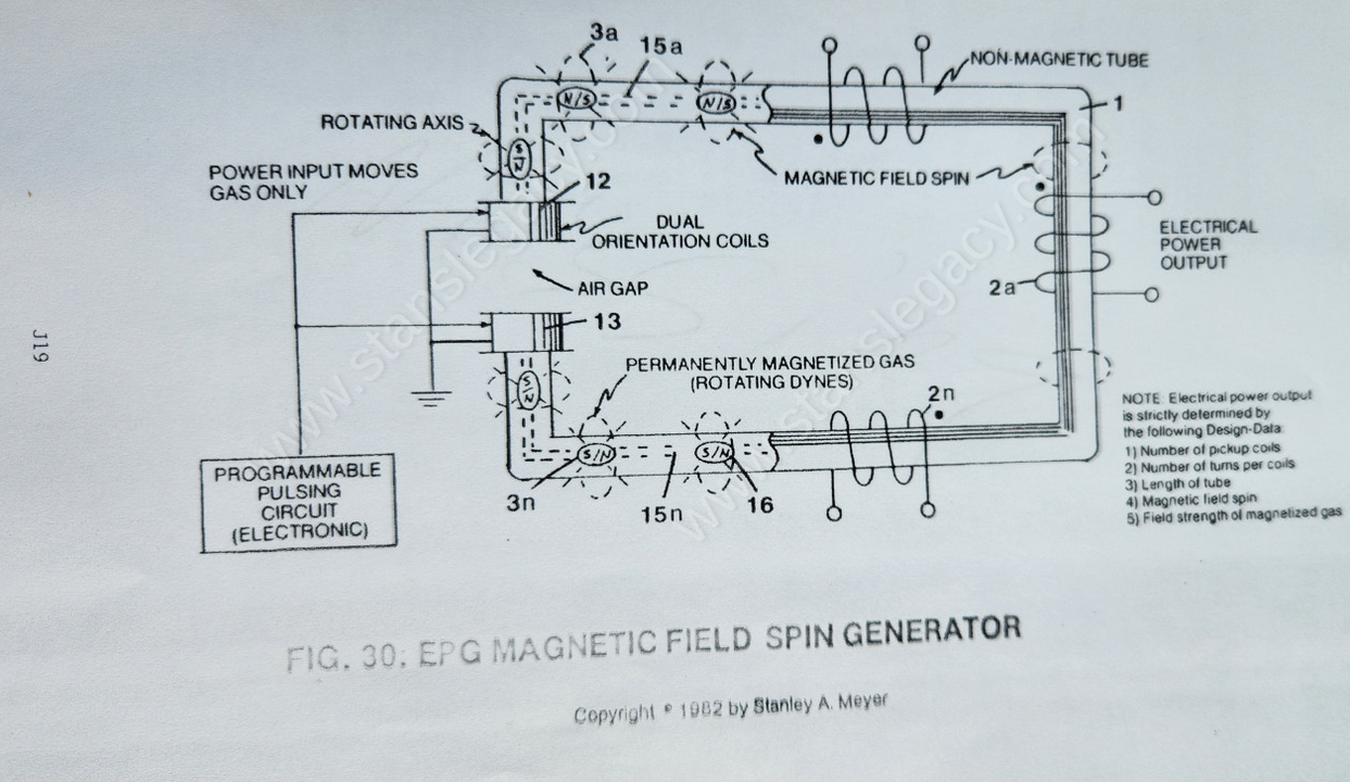
Said magnetic field (4) reforming after exiting said Stator Assembly (30). · ELECTRICAL PARTICLE GENERATOR
-
Pulse-frequency electrical output (23 of Figure 30 as to Figure 27) is strictly determined by the pulse-rate of said orientation coils (12/13). · ELECTRICAL PARTICLE GENERATOR
-
The figure it sits on · ELECTRICAL PARTICLE GENERATOR
-
The figure it sits on · ELECTRICAL PARTICLE GENERATOR
-
The figure it sits on · ELECTRICAL PARTICLE GENERATOR
Where it is named · 18
ELECTRICAL PARTICLE GENERATOR 18×
-
Electromagnetic Pump Assembly (30)
Said mechanical drive system (20) and/or Electromagnetic Pump Assembly (30) can be used separately, joined together, or periodically spaced around said tubular structure (1) as to (8).
-
Electromagnetic Pump Assembly (30)
Longitudinal movement (moving permanently magnetized fluid-medium inside said tubular pathway) of said magnetic field (4 of Figure 26) is simply accomplished when said Electro/mechanical Pump Assembly (20) of Figure 27 and/or Electromagnetic Pump Assembly (30) of Figure 28 is energized for operability.
-
Power Drive System (20/30)
… ar direction (4 of Figure 26, 27, and 28) as described above, a Spiral Divider (9) of Figure 26F is now inserted into said tubular pathway (1) leading away from and connecting said Power Drive System (20/30), said Spiral Divider (9) passing through said pickup coil-array (2a xxx 2n), said Spiral Divider (9) terminating at and not passing through said Power Drive System (20/30), as shown in Figure (26F) a …
-
Power Drive System (20/30)
… ing said Power Drive System (20/30), said Spiral Divider (9) passing through said pickup coil-array (2a xxx 2n), said Spiral Divider (9) terminating at and not passing through said Power Drive System (20/30), as shown in Figure (26F) as to Figures (26, 28, and 33).
-
Electromagnetic Pump Assembly (30)
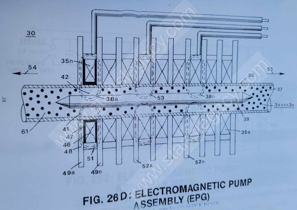
The Electromechanical actuator (Electromagnetic Pump Assembly (30)) attached to said tubular pathway (1) operates as a direct-drive principle of a linear induction motor.
-
outside core (30)
Said lubrication is also applied to the outside core (30) above Section E) intermittent with said magnetic-fluid mass lines (3a xxx 3n) allows said rod-shape particle-mass to move through said stator assembly (30).
-
stator assembly (30)
Said lubrication is also applied to the outside core (30) above Section E) intermittent with said magnetic-fluid mass lines (3a xxx 3n) allows said rod-shape particle-mass to move through said stator assembly (30).
-
stator assembly (30)
The linear motion of said moving fluid-medium (3a xxx 3n) through the stator assembly (30) is shown in Figure 26A to Figure 33F of Figure 26B which is essentially a series of coils as stator assembly (30) which is essentially a series of coils as stator assembly (35a xxx 35n) of Figure 26C as to Figure 26 and Figure 33.
-
stator assembly (30)
The linear motion of said moving fluid-medium (3a xxx 3n) through the stator assembly (30) is shown in Figure 26A to Figure 33F of Figure 26B which is essentially a series of coils as stator assembly (30) which is essentially a series of coils as stator assembly (35a xxx 35n) of Figure 26C as to Figure 26 and Figure 33.
-
Stator Assembly (30a xxx 30n)
Three-phase operations. Stator Assembly (30a xxx 30n) can be combined or built specially for higher forces.
-
single-phase units (30)
Fluid-medium (3) velocity: Fluid-mass acceleration occurs in less than 10 milliseconds and reaches a controlled speed (or velocity) during recycling. The time or distance needed to perform normal operational speed of fluid-velocity depends upon net force "applied" and fluid-mass being moved. Normal operating velocity is 30 fps for single-phase units (30) and 90 fps for three-phase units (30/30/30).
-
three-phase units (30/30/30)
Fluid-medium (3) velocity: Fluid-mass acceleration occurs in less than 10 milliseconds and reaches a controlled speed (or velocity) during recycling. The time or distance needed to perform normal operational speed of fluid-velocity depends upon net force "applied" and fluid-mass being moved. Normal operating velocity is 30 fps for single-phase units (30) and 90 fps for three-phase units (30/30/30).
-
coil-array (30/30)
A second magnetic bar key (39) is inserted into said tubular pathway (36) and properly aligned to said coil-array (30/30)... forming an air gap (42) between said tubular surface (36) and said Magnetic Key Assembly (39)... completing the field effect forming said cavity (41)... and structuring pulsing effect itself (35).
-
coil circuit assembly (30)
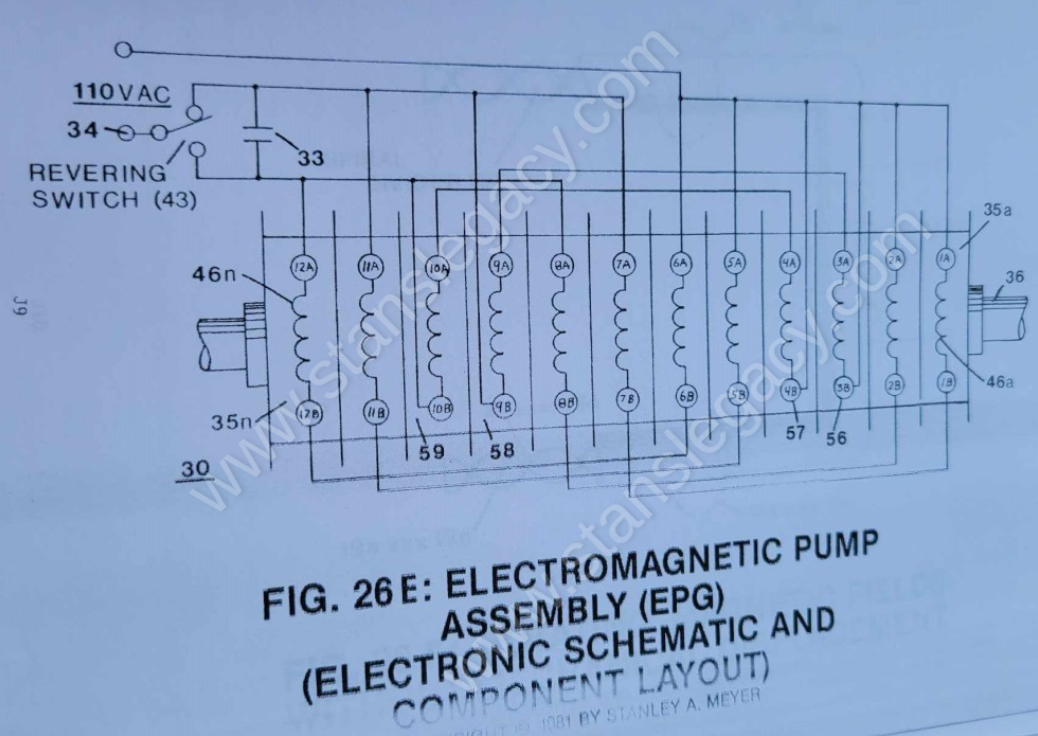
Said pulse circuit (35) is now placed end-to-end (35a xxx 35n) to said coil circuit assembly (30) for magnetic force, as illustrated in Figure 26E and Figure 28 and Figure 33.
-
Stator assembly (30)
To obtain maximum operational efficiency of said Stator assembly (30), said magnetic keeper-bar (39) also acts as a magnetic field spoiler by disrupting particle alignment (15a xxx 15n of Figure 30)... collapsing magnetic field (4/11) prior to particle entrance into said Stator Assembly (30).
-
Stator Assembly (30)
To obtain maximum operational efficiency of said Stator assembly (30), said magnetic keeper-bar (39) also acts as a magnetic field spoiler by disrupting particle alignment (15a xxx 15n of Figure 30)... collapsing magnetic field (4/11) prior to particle entrance into said Stator Assembly (30).
-
Stator Assembly (30)
Said magnetic field (4) reforming after exiting said Stator Assembly (30).