Figure (26A)
Attenuating Gas-field Copyright
How it is written
- (26A) 8×
Drawings 2
-
Captioned as this figure · ELECTRICAL PARTICLE GENERATOR
-
Beside the passage · ELECTRICAL PARTICLE GENERATOR
On this figure 11
- 2 Coil-Array
- 3 Fluid-Medium
- 4 Magnetic Field
- 11 Magnetic Field
- 12 Orientation Coils
- 13 Orientation Coils
- 17 Pulsating Magnetic Field
- 18 Pulsating Magnetic Field
- 19 Pathway Channels
- 30 Stator Assembly
- 31 EMF field
Where it is named · 8
ELECTRICAL PARTICLE GENERATOR 8×
-
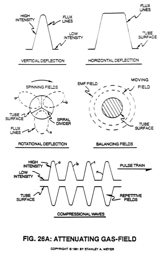
Pulsing said Orientation-coils (12/13) quickly causes a vertical deflection (17a xxx 17n of Figure 26A) of said magnetic field (4/11).
-
Pulsing said Orientation-coils slowly causes a horizontal deflection (18a xxx 18n of Figure 26A) of said magnetic field (4/11).
-
To move more magnetic flux lines through said pickup coil-array (2a xxx 2n) while keeping said particle (3a xxx 3n) velocity constant, said Spiral Divider (9) of Figure 26F is now subdivided into many pathway channels (19a xxx 19n), as illustrated in Figure 26A sub-titled "Rotational Deflection."
-
The multi-channel spiral divider (19a xxx 19n) is composed of any type of material (such as electrical steel M27) that will "NOT" become permanently magnetized (when exposed to said moving magnetic field (4)) when "shunting" said magnetic field (11a xxx 11n), as shown in Figure 26A sub-titled "Rotational Deflection."
-
See Figure 26A subtitled "Compression Waves."
-
After EMF field collapses, magnetic pulsating field (29 of Figure 26) is reformed once again... starting and continuing the on/off switching process in a sequential manner as pictorially illustrated in Figure 26A.
-
The linear motion of said moving fluid-medium (3a xxx 3n) through the stator assembly (30) is shown in Figure 26A to Figure 33F of Figure 26B which is essentially a series of coils as stator assembly (30) which is essentially a series of coils as stator assembly (35a xxx 35n) of Figure 26C as to Figure 26 and Figure 33.