Figure (26)
EPG Principle
How it is written
- (26) 12× with (26) Pickup coil-array phasing
- (11 of Figure 26) 1× with (11) Magnetic Field
- (29 of Figure 26) 1× with (29) Concentric Magnetic Ring
- (3 of Figure 26) 1× with (3) Fluid-Medium
- (4 of Figure 26) 1× with (4) Magnetic Field
- (4 of Figure 26, 27, and 28) 1×
Drawings 12
-
Captioned as this figure · ELECTRICAL PARTICLE GENERATOR
-
When EMF field (31) is formed, said pulsating magnetic field (29) forming concentric ring (29) is turned off (switched off). · ELECTRICAL PARTICLE GENERATOR
-
Captioned as this figure · ELECTRICAL PARTICLE GENERATOR
-
Carries this number · ELECTRICAL PARTICLE GENERATOR
-
Carries this number · ELECTRICAL PARTICLE GENERATOR
-
Carries this number · ELECTRICAL PARTICLE GENERATOR
-
Carries this number · ELECTRICAL PARTICLE GENERATOR
-
Carries this number · ELECTRICAL PARTICLE GENERATOR
-
Carries this number · ELECTRICAL PARTICLE GENERATOR
-
Carries this number · ELECTRICAL PARTICLE GENERATOR
-
Carries this number · ELECTRICAL PARTICLE GENERATOR
-
Carries this number · ELECTRICAL PARTICLE GENERATOR
On this figure 7
- 1 Tubular Pathway
- 2 Coil-Array
- 3 Fluid-Medium
- 4 Magnetic Field
- 10 Particle Accelerator Assembly
- 11 Magnetic Field
- 29 Concentric Magnetic Ring
Where it is named · 17
ELECTRICAL PARTICLE GENERATOR 17×
-
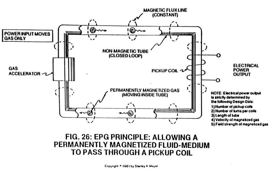
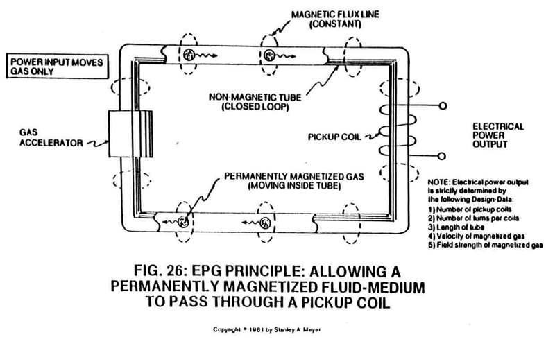
Take a non-magnetic tube (material that will not become permanently magnetized when exposed to a magnetic field and having the capability of distorting said magnetic field through said tubular material without signal distortion… such as aluminum, brass, glass, and/or plastics) and form a closed loop pathway (without open ends), as illustrated in (1) of Figure 26 through Figure 30.
-
Insert into and affixed a Particle Accelerator Assembly (10) to said closed loop tube (1) as to (8), locating said Particle Accelerator Assembly on opposite end of tube (1) away from said pickup windings (2 xxx 2n), as shown in Figure 26.
-
Said Particle Accelerator Assembly (10) causes and propels a permanent magnetic fluid-medium (3 of Figure 26) (liquid slurry or gases) to move toward, through, and beyond said pickup coils (2) for recycling, as illustrated in Figure 26.
-
Said Particle Accelerator Assembly (10) causes and propels a permanent magnetic fluid-medium (3 of Figure 26) (liquid slurry or gases) to move toward, through, and beyond said pickup coils (2) for recycling, as illustrated in Figure 26.
-
Said Particle Accelerator Assembly (10) causes and propels a permanent magnetic fluid-medium (3 of Figure 26) (liquid slurry or gases) to move toward, through, and beyond said pickup coils (2) for recycling, as illustrated in Figure 26.
-
… causing said material (3) to become permanently magnetized...forming a longitudinal field (4) of Figure 26 emitting from said tubular pathway (1).
-
Longitudinal movement (moving permanently magnetized fluid-medium inside said tubular pathway) of said magnetic field (4 of Figure 26) is simply accomplished when said Electro/mechanical Pump Assembly (20) of Figure 27 and/or Electromagnetic Pump Assembly (30) of Figure 28 is energized for operability.
-
Longitudinal movement (moving permanently magnetized fluid-medium inside said tubular pathway) of said magnetic field (4 of Figure 26) is simply accomplished when said Electro/mechanical Pump Assembly (20) of Figure 27 and/or Electromagnetic Pump Assembly (30) of Figure 28 is energized for operability.
-
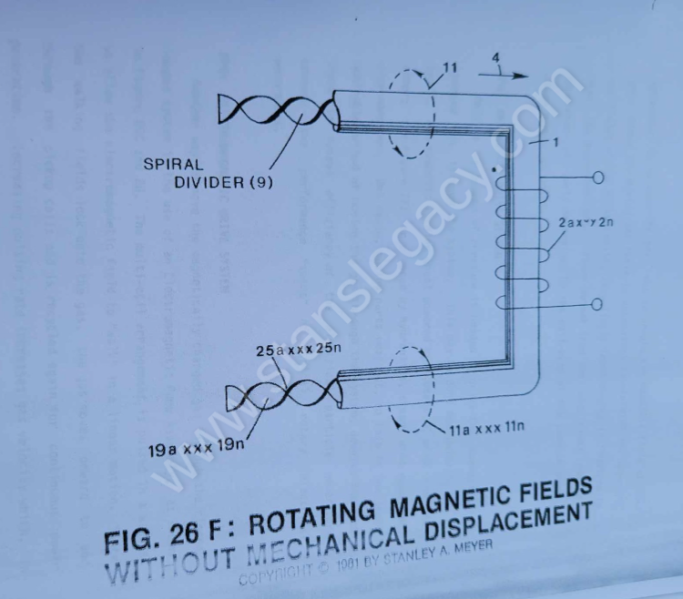
To spin or rotate said magnetic field (4) as to (11 of Figure 26) on its longitudinal axis while moving in a linear direction (4 of Figure 26, 27, and 28) as described above, a Spiral Divider (9) of Figure 26F is now inserted into said tubular pathway (1) leading a …
-
To spin or rotate said magnetic field (4) as to (11 of Figure 26) on its longitudinal axis while moving in a linear direction (4 of Figure 26, 27, and 28) as described above, a Spiral Divider (9) of Figure 26F is now inserted into said tubular pathway (1) leading …
-
To spin or rotate said magnetic field (4) as to (11 of Figure 26) on its longitudinal axis while moving in a linear direction (4 of Figure 26, 27, and 28) as described above, a Spiral Divider (9) of Figure 26F is now inserted into said tubular pathway (1) leading away from and connecting said Power Drive System (20/30), said Spiral Divider (9) passing …
-
To spin or rotate said magnetic field (4) as to (11 of Figure 26) on its longitudinal axis while moving in a linear direction (4 of Figure 26, 27, and 28) as described above, a Spiral Divider (9) of Figure 26F is now inserted into said tubular pathway (1) leading away from and connecting said Power Drive System (20/30), said Spiral Divider …
-
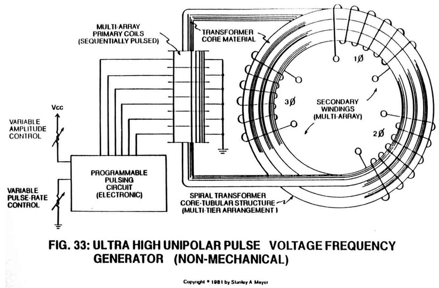
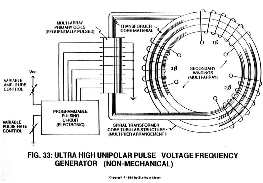
The magnetic pulsing process simply spins the dyne-axis of said particles (3a xxx 3n) to oscillate and attenuate a permanent magnetic field (4/11 as to 17/18), as illustrated in Figure 30 as to Figure 26 through Figure 33.
-
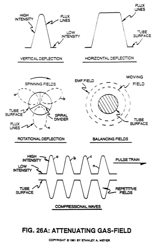
After EMF field collapses, magnetic pulsating field (29 of Figure 26) is reformed once again... starting and continuing the on/off switching process in a sequential manner as pictorially illustrated in Figure 26A.
-
After EMF field collapses, magnetic pulsating field (29 of Figure 26) is reformed once again... starting and continuing the on/off switching process in a sequential manner as pictorially illustrated in Figure 26A.
-
To bypass and overcome the mechanical limitation of said Turbine Pump Assembly (20 of Figure 27), the Electromagnetic Pump Assembly (30 as to Figure 26F) in relationship to Figure 26C is utilized to propel said fluid-medium (3a xxx 3n) of Figure 26 as to Figure 26C.
-
The linear motion of said moving fluid-medium (3a xxx 3n) through the stator assembly (30) is shown in Figure 26A to Figure 33F of Figure 26B which is essentially a series of coils as stator assembly (30) which is essentially a series of coils as stator assembly (35a xxx 35n) of Figure 26C as to Figure 26 and Figure 33.