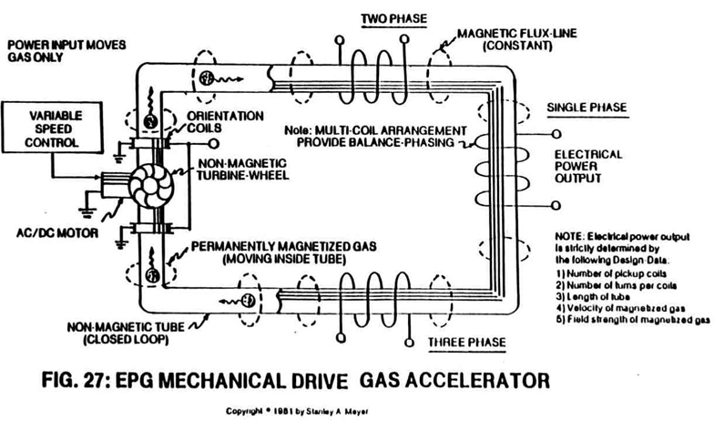
Figure (27)
Figure (27)
How it is written
- (27) 8× with (27) Unidirectional pulsing
- (20 of Figure 27) 2× with (20) Power Drive System
- (12/13 of Figure 27) 1×
- (14 of Figure 27) 1× with (14) Variable Pulse Voltage Frequency Generator
- (23 of Figure 30 as to Figure 27) 1× with Figure (30) EPG Mechanical Drive Gas Accelerator C
Drawings 3
-
Carries this number · ELECTRICAL PARTICLE GENERATOR
-
Pulse-frequency electrical output (23 of Figure 30 as to Figure 27) is strictly determined by the pulse-rate of said orientation coils (12/13). · ELECTRICAL PARTICLE GENERATOR
-
When EMF field (31) is formed, said pulsating magnetic field (29) forming concentric ring (29) is turned off (switched off). · ELECTRICAL PARTICLE GENERATOR
On this figure 12
- 1 Tubular Pathway
- 3 Fluid-Medium
- 4 Magnetic Field
- 8 Non-Magnetic Tubular Pathway
- 11 Magnetic Field
- 12 Orientation Coils
- 13 Orientation Coils
- 14 Variable Pulse Voltage Frequency Generator
- 15 Electromagnetic Field Alignment
- 20 Power Drive System
- 21 Non-Magnetic Turbine Wheel
- 22 Power Train linkage
Where it is named · 13
ELECTRICAL PARTICLE GENERATOR 13×
-
A Mechanical Accelerator Drive Assembly (20 of Figure 27) utilizes a non-magnetic turbine wheel (21) to physically move said magnetic fluid-medium (3) inside said tubular pathway (1).
-
A Mechanical Accelerator Drive Assembly (20 of Figure 27) utilizes a non-magnetic turbine wheel (21) to physically move said magnetic fluid-medium (3) inside said tubular pathway (1).
-
Power Train linkage (22) to said non-magnetic turbine wheel (21 of Figure 27 can take different forms:
-
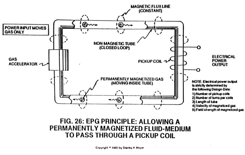
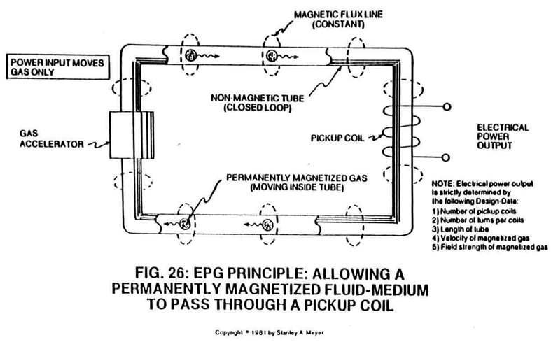
Longitudinal movement (moving permanently magnetized fluid-medium inside said tubular pathway) of said magnetic field (4 of Figure 26) is simply accomplished when said Electro/mechanical Pump Assembly (20) of Figure 27 and/or Electromagnetic Pump Assembly (30) of Figure 28 is energized for operability.
-
To pulsate or vary said rotational field (11) moving in a linear direction (4), Dual-Orientational coils (12/13 of Figure 27) are now inserted into said tubular pathway on opposite side of Electromechanical Drive System (20), away from said pickup coil-array (2a xxx 2n), as illustrated in Figure (27) as to Figure 30.
-
To pulsate or vary said rotational field (11) moving in a linear direction (4), Dual-Orientational coils (12/13 of Figure 27) are now inserted into said tubular pathway on opposite side of Electromechanical Drive System (20), away from said pickup coil-array (2a xxx 2n), as illustrated in Figure (27) as to Figure 30.
-
First, when electrically energized, said dual-coils (12/13) stabilize said magnetic field (4/11) since said turbine wheel (21 of assembly 20) disrupts the electromagnetic field alignment (15a xxx 15n) (electromagnetic attraction force) between said permanently magnetized particles (3a xxx 3n) moving inside non-magnetic tubular pathway (1 as to 8), see Figure 27 as to Figure 30.
-
Pulse-frequency electrical output (23 of Figure 30 as to Figure 27) is strictly determined by the pulse-rate of said orientation coils (12/13).
-
Variable Pulse Voltage Frequency Generator (14 of Figure 27) (Figure 9XB as to Figure 9XAA) is used to trigger or energize said pulsing coils at the same time (12/13) during particle (3) deflection.
-
Variable Pulse Voltage Frequency Generator (14 of Figure 27) (Figure 9XB as to Figure 9XAA) is used to trigger or energize said pulsing coils at the same time (12/13) during particle (3) deflection.
-
To bypass and overcome the mechanical limitation of said Turbine Pump Assembly (20 of Figure 27), the Electromagnetic Pump Assembly (30 as to Figure 26F) in relationship to Figure 26C is utilized to propel said fluid-medium (3a xxx 3n) of Figure 26 as to Figure 26C.
-
To bypass and overcome the mechanical limitation of said Turbine Pump Assembly (20 of Figure 27), the Electromagnetic Pump Assembly (30 as to Figure 26F) in relationship to Figure 26C is utilized to propel said fluid-medium (3a xxx 3n) of Figure 26 as to Figure 26C.