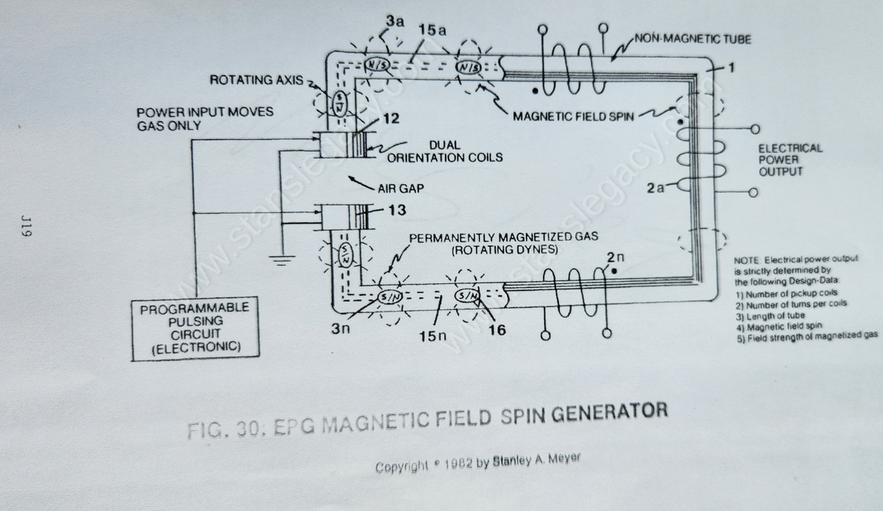
Figure (30)
EPG Mechanical Drive Gas Accelerator C
How it is written
- (30) 6× with (30) Stator Assembly
- (23 of Figure 30 as to Figure 27) 1× with Figure (27)
Drawings 5
-
Pulse-frequency electrical output (23 of Figure 30 as to Figure 27) is strictly determined by the pulse-rate of said orientation coils (12/13). · ELECTRICAL PARTICLE GENERATOR
-
Carries this number · ELECTRICAL PARTICLE GENERATOR
-
Carries this number · ELECTRICAL PARTICLE GENERATOR
-
Carries this number · ELECTRICAL PARTICLE GENERATOR
-
Said magnetic field (4) reforming after exiting said Stator Assembly (30). · ELECTRICAL PARTICLE GENERATOR
On this figure 11
- 2 Coil-Array
- 3 Fluid-Medium
- 4 Magnetic Field
- 11 Magnetic Field
- 15 Electromagnetic Field Alignment
- 17 Pulsating Magnetic Field
- 18 Pulsating Magnetic Field
- 20 Power Drive System
- 27 Unidirectional pulsing
- 30 Stator Assembly
- 39 Magnetic Key Assembly
Where it is named · 7
ELECTRICAL PARTICLE GENERATOR 7×
-
Take a non-magnetic tube (material that will not become permanently magnetized when exposed to a magnetic field and having the capability of distorting said magnetic field through said tubular material without signal distortion… such as aluminum, brass, glass, and/or plastics) and form a closed loop pathway (without open ends), as illustrated in (1) of Figure 26 through Figure 30.
-
To pulsate or vary said rotational field (11) moving in a linear direction (4), Dual-Orientational coils (12/13 of Figure 27) are now inserted into said tubular pathway on opposite side of Electromechanical Drive System (20), away from said pickup coil-array (2a xxx 2n), as illustrated in Figure (27) as to Figure 30.
-
First, when electrically energized, said dual-coils (12/13) stabilize said magnetic field (4/11) since said turbine wheel (21 of assembly 20) disrupts the electromagnetic field alignment (15a xxx 15n) (electromagnetic attraction force) between said permanently magnetized particles (3a xxx 3n) moving inside non-magnetic tubular pathway (1 as to 8), see Figure 27 as to Figure 30.
-
The magnetic pulsing process simply spins the dyne-axis of said particles (3a xxx 3n) to oscillate and attenuate a permanent magnetic field (4/11 as to 17/18), as illustrated in Figure 30 as to Figure 26 through Figure 33.
-
To obtain maximum operational efficiency of said Stator assembly (30), said magnetic keeper-bar (39) also acts as a magnetic field spoiler by disrupting particle alignment (15a xxx 15n of Figure 30)... collapsing magnetic field (4/11) prior to particle entrance into said Stator Assembly (30).