(8) · also written as a run, 8a xxx 8n
Non-Magnetic Tubular Pathway
Also written tubular pathway · spiral pathway · pathway · spiral configuration · tubular legs · tubular-legs
Where it is first named
Said tubular pathway (1) can be extended into a spiral configuration (8) of Figure 33.
How it is written
- (8a xxx 8n) 5×
- (8) 3×
- (1 as to 8) 1×
- (8 of Figure 33) 1× with Figure (33)
8a xxx 8n is Meyer's shorthand for a run of the same thing: 8a is the first, 8n the last, and the x's stand for however many lie between. Every stage of the run is this one numeral.
Drawings 1
-
The figure it sits on · ELECTRICAL PARTICLE GENERATOR
Where it is named · 10
ELECTRICAL PARTICLE GENERATOR 10×
-
spiral configuration (8)
Said tubular pathway (1) can be extended into a spiral configuration (8) of Figure 33.
-
spiral pathway (8)
Said pickup coil (2) is placed around said spiral pathway (8) of Figure 33 to form a coil-array (2a xxx 2n).
-
tubular pathway (8)
… y filled with said permanently magnetized material (3), said pickup coil-array (2a xxx 2n) is electrically energized to produce an electromagnetic field that completely surrounds said tubular pathway (8) of Figure 33, exposing said magnetic material (3) to said electromagnetic field... …
-
non-magnetic tubular pathway (1 as to 8)
First, when electrically energized, said dual-coils (12/13) stabilize said magnetic field (4/11) since said turbine wheel (21 of assembly 20) disrupts the electromagnetic field alignment (15a xxx 15n) (electromagnetic attraction force) between said permanently magnetized particles (3a xxx 3n) moving inside non-magnetic tubular pathway (1 as to 8), see Figure 27 as to Figure 30.
-
To increase said magnetic flux lines (11a xxx 11n) still further, said pathway (1) is now spiraled (8 of Figure 33) (in spaced relationship to each other) inside said pickup coil-array (2a xxx 2n), as illustrated in Figure 33 as to cross-sectional drawing titled "Multi-tubular array"of Figure 28A.
-
The greater number of spiral-turns (8a xxx 8n) the greater number of right-hand lines transverses said pickup coil array (2a xxx 2n) during pulse-form stage.
-
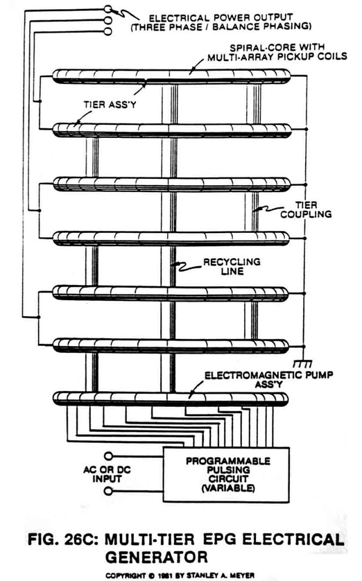
The number of "shunting" magnetic fields (11a xxx 11n) times (x) the number of spiral pathways (8a xxx 8n) determine the magnetic field strength of said EPG system of Figure 26C.
-
tubular-legs (8a xxx 8n)
The number of tubular-legs (8a xxx 8n) spiraled inside said pickup coil-array (2a xxx 2n). The number of multi-rotational fields (11a xxx 11n) formed per turns of tubular legs (8a xxx 8n).
-
tubular legs (8a xxx 8n)
The number of tubular-legs (8a xxx 8n) spiraled inside said pickup coil-array (2a xxx 2n). The number of multi-rotational fields (11a xxx 11n) formed per turns of tubular legs (8a xxx 8n).
-
pathway (8a xxx 8n)
… e opposition to the movement of said magnetic fluid-medium during power on-stage, said pickup coil array (2a xxx 2n) of Figure 33 as to Figure 26F is placed and aligned end-to-end around said pathway (8a xxx 8n) for the purpose of coupling and forming a single and continuous magnetic field (31) or any type of electromagnetic field emanating from said pickup coil-array (during duty loading) is wrapped and positioned around said pickup coil-array (2a xxx 2n)... …