8-3 - Electrical Voltage-Pulse Wave-Transmission
Electrical Voltage-Pulse Wave-Transmission (583a xxx 583n), now formed, occurs along Electrical Conductance Zone (587) since applied Electrical Pulse Voltage amplitude (Vo - 64a - 64b- 64c - Vn) is time responsive (T1/T2a - T3 – T1/T2n) to incoming gated Voltage Pulse Frequency (49a xxx - 1'3 - xxx 49n).
Each Voltage Pulse duration time-period (T1 on time) from start to finish is directly related to applied Voltage-Pulse Amplitude (Vo xxx Vn) and reoccurring Voltage Pulse Frequency (49a xxx 49n) forming "Unipolar Voltage Pulse-Wave" (583) from zero voltage ground state (Vo) to a predetermined Voltage Level ( xxx 64 x - 64y - 64z - Vn) on the leading edge of the Voltage Pulse-Wave (Vpa) and, then, reversing voltage up swing to drop on the trailing edge (Vpb), completing Voltage-wave (583).
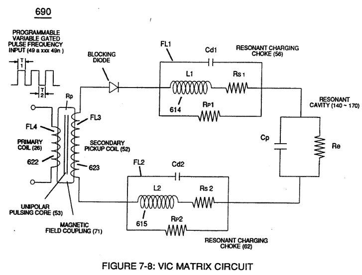
The newly established leading voltage edge (Vpa) and trailing voltage edge (Vpb) being uniform in shape/configuration since both Resonant Charging Chokes (56/Z2 – 62/Z3) resistive values are the same (Typically 11.6 kΩ each) and incoming signal (49a xxx 49n) is electrically linked with Water-Gap Capacitor (Cp) of Figure (7-8) having dielectric liquid of Water (85) there between.
|
Figure (7-8)
|
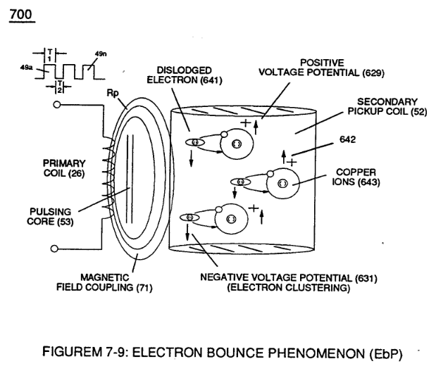
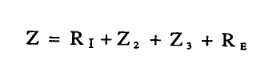
Thereby, preventing coil-ringing during each pulse off-time ...allowing Electron Bounce Phenomenon (EbP) to occur without amp influxing within VIC Matrix Circuit (690) of Figure (7-8) as so governed by Circuit Resistance Equations (Eq. 9) which, inactivated electrical-state, allows positive Voltage Pulse-Wave (583) to be duplicated in succession to form Voltage Pulse Train (66 - 583a xxx 583n), as illustrated in (770) of Figure (8-1).
Circuit Resistance Equations (Eq. 9):
|
(770) of Figure (8-1)
|
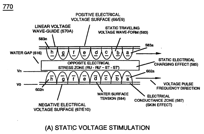
Opposite negative Voltage Pulse Train (67 - 602a xxx 602n) is similarly formed since "Electron Clustering Effect" (631) of Figure (7-9) produces a "Negative Electrical Voltage Intensity (67) in equal magnitude to the "Positive Electrical Voltage Intensity (66) during each/repetitious magnetic pulse-cycle (Rp/71). Remember, Secondary Voltage pickup coil (52) of Figure (7-8) displaces and separates Resonant Charging Chokes (56/62) on opposite end of said Secondary Pickup Coil (52).
|
(631) of Figure (7-9)
|
(52) of Figure (7-8)
|