LC Circuit
Resonant Charging Choke (C) in series with Excitor-array (E1/E2) forms an inductor-capacitor circuit (LC) since the Excitor-Array (ER) acts or performs as an capacitor during pulsing operations, as illustrated in Figure (1-2) as to Figure (1-1).
|
Figure (1-2)
|
Figure (1-1)
|
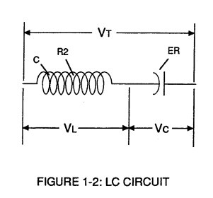
The Dielectric Properties (insulator to the flow of amps) of natural water (dielectric constant being 78.54 @ 25c) between the electrical plates (E1/E2) forms the capacitor (ER).
Water now becomes part of the Voltage Intensifier Circuit in the form of "resistance" between electrical ground and pulse-
frequency positive-potential
... helping to prevent electron flow within the pulsing circuit (AA) of Figure 1-1.
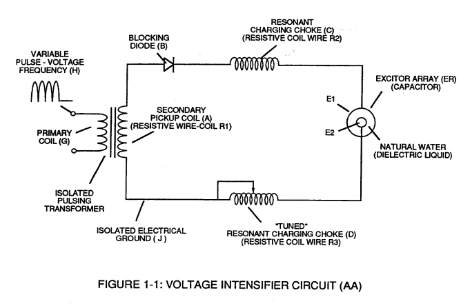
The Inductor (C) takes on or becomes an Modulator Inductor which steps up an oscillation of an given charging frequency with the effective capacitance of an pulse-forming network in order to charge the voltage zones (E1/E2) to an higher potential beyond applied voltage input.
The Inductance (C) and Capacitance (ER) properties of the LC circuit is therefore "tuned" to resonance at a certain frequency.
The Resonant Frequency can be raised or lowered by changing the inductance and/or the capacitance values.
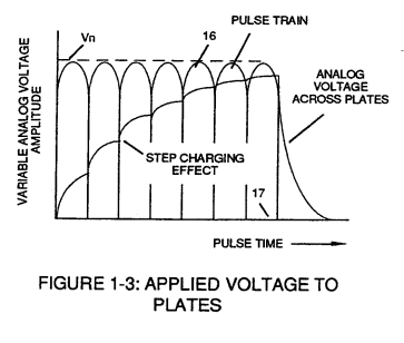
The established resonant frequency is, of course, independent of voltage amplitude, as illustrated in Figure (1-3) as to Figure (1-4).
|
Figure (1-3)
|
Figure (1-4)
|

The value of the Inductor (C), the value of the capacitor (ER), and the pulse-frequency of the voltage being applied across the LC circuit determines the impedance of the LC circuit.
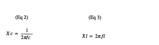
The impedance of an inductor and a capacitor in series, Z series is given by (Eq 1)
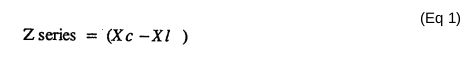
Where:
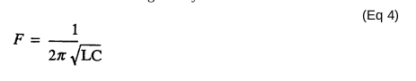
The Resonant Frequency (F) of an LC circuit in series is given by (Eq 4)
Ohm's Law for LC circuit in series is given by: