Quartz Tube Configuration & Operational Parameters
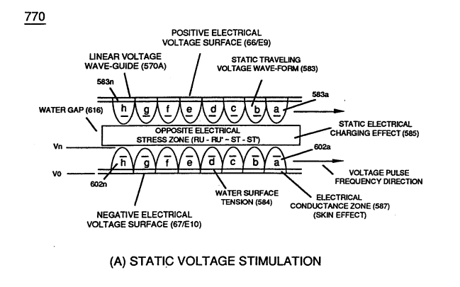
 Exposing the hydrogen atoms to applied Static Voltage Stimulation (770) of Figure (8-1) causes the Static Electrical Charging Effect (585) to set up "Voltage Tickling of State Space" which takes the hydrogen atom (s) from "Quiescent State" (Qs) to "Active State" (As) and then back again to "Quiescent State" (Qs) once applied unipolar pulse-wave (583/602) goes through Voltage Pulsing Cycle (Vpwf) from "Ground State" (Gs) to Voltage Peak potential (Vpp) (780) of Figure (8-2A) and then returns to "Ground State" (Gs) for continued repetitive Voltage-Pulsing (583/602a xxx 583/602n)
... forming Pulse Wave Frequency (Pwf), as so illustrated in (780) of Figure (8-2) as to (770) of Figure (8-1).
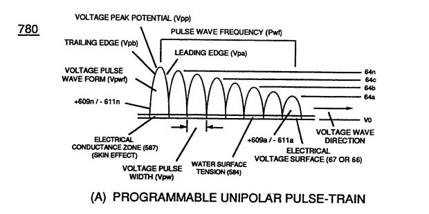 The resultant Flex-Density (Fd) of the hydrogen atom(s) is, now, directly related to applied Voltage Amplitude (64a - 64b - 64c - 64n) of Figure (8-2A) which directly determines the Field Strength (Fs) of Static Electrical Charging Effect (Sece)(585).
The Voltage Pulse Field (Vpf) (forming leading and trailing edges of each Voltage Pulse) determines the duration of the Static Electrical Charging Effect (Sece) being superimposed onto the Hydrogen Atom (s) during each Voltage Pulsing Cycle (Vpwf).
The Electrical Conduction Zone (587) (Skin Effect) between the dielectric gas medium (919) and the Electrical Contact Surface of the inside surface area of the Voltage Wave-Guides (66/67) allows Unipolar Pulse Train (583a/602a-583b/602b - 583n/602n) to travel the entire length of the Voltage Wave Guides that make up Voltage Zones (66/E9 – 67/E10).
Static Voltage Stimulation (770) of Figure (8-1A) is where Voltage Peak Potential (Vpp) remains constant during Voltage Pulse Formation (VpbNpa) to keep reforming Flex-Density Potential (Fdpa xxx Fdpn) from going beyond a certain point away from Static State of Equilibrium (Esse)
[Quiescent State of the hydrogen atom (s)];
whereby,
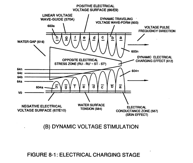
Dynamic Voltage Stimulation (770) of Figure (8-1B) continues to go farther and farther away from the State of Equilibrium (Esse) during each and every Voltage Pulsing Cycle (Vpf), as so illustrated in (770) of Figure (8-1B}
... establishing variable Dynamic Electrical Charging Effect (612).
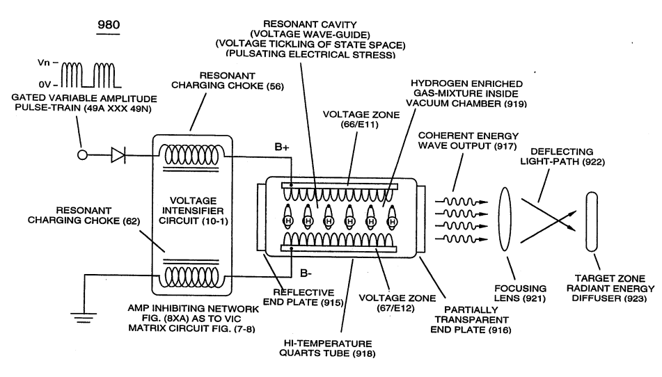
In both cases, Static Voltage Stimulation (770) of Figure (8-1A) and Dynamic Voltage Stimulation (770) of Figure (8-1B) incorporates the use of Positive Electrical Voltage Potential (B+) (Ell) and Negative Electrical Voltage Potential (B-) (EI2) to form synchronized diametrically opposed Voltage Gate-Pulse (Vgp) (583/602) across Vacuum Gap (Vc)
... thereby, establishing functional parameters of Optical Thermal Lens (980) of Figure (10-2) when Voltage Intensifier Circuit (VIC Circuit) (10-1) is electrically connected to Voltage Zones (ER) (66/Ell-67/E12).
Remember, Voltage-Sync Gate-Pulse (Vgp) produces opposite electrical attraction forces (B+/ST-ST' - B-/RU-RU') of Figure (5-1) that are not consumed in an electronic circuit.

