Resonant Action
Subjecting and exposing water molecule (85) to even higher voltage levels (xxx Vn) (up to and beyond several thousand volts) causes water bath (91) of Figure (3-30) as to Figure (3-25) to go into a state of ionization by allowing opposite polarity forces (TT') and (UU') to eject one or more electrons (92a xxx 92n) from water bath atoms (93).
|
Figure (3-30)
|
Figure (3-25)
|
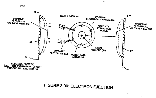
Intensified electrical attraction force (TT') causes dislodged negative charged electrons (92) to migrate to positive voltage-plate (E1) while electrical attraction force (UU') causes positive charged atom nucleus (94) to travel toward negative voltage-plate (E2).
Applied electrical attraction force (TT') and (UU') always being of equal voltage intensity but opposite in electrical polarity as voltage amplitude (65) is attenuated.
Replication of higher voltage forces (TT') and (UU') during pulsing operations causes a continued release of other electrons (92a xxx 92n) from other water bath atoms (93a xxx 93n) which, in practice, increases electrical charges of water bath (91) since water bath (91) is a dielectric liquid.
 Water bath atoms (93a xxx 93n) having missing electrons (92) take-on a positive electrical charge (95) which is subject to and moved by negative electrical force (UU'); whereby, the liberated and free floating negative charge electrons (92) are subject to and moved by positive electrical force (TT').
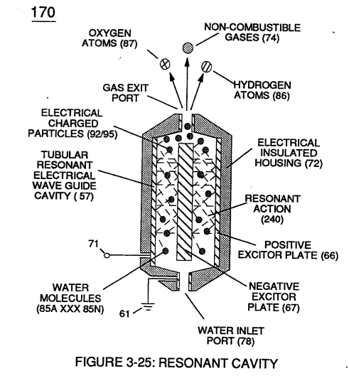
Applied together, electrical forces (TT') and (UU'), now, causes these moving electrically charged particles to superimpose a physical impact unto electrical polarization process (160), as shown in (170) of Figure (3-25)
... thereby, increasing gas-yield (88) still further.
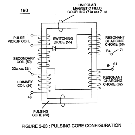 By attenuating voltage amplitude (Vo xxx Yn) in conjunction with pulse-width (65a xxx 65n) allows voltage intensifier circuit (190) of Figure (3-23) to tune-in and match the resonant characteristics or resonant frequency of water bath (91) since water bath (91) always maintains its dielectric properties during pulsing operations.
At resonance, electrical polarization process (160) interacts uniformly with liberated charged particles (92/95) of Figure (3-25) to obtain a even higher gas-yield (88) at maximum voltage deflection (xxx Vn).
The established resonant frequency is most generally in the audio range from 1 kHz up to and beyond 10 kHz; and is dependent upon the amount of contaminants in natural water.
Oscillating and superimposing electrically charged particles unto the Electrical Polarization process at a given pulse-frequency is, now, herein called "Resonant Action", as illustrated in (240) of Figure (3-25).
To reach maximum gas-yield (88) resonant cavity (170) of Figure (3-25) is shaped into a tubular structure (typically 0.50 inch diameter tube inserted into 0.75 inch diameter tube having a .0625 concentric air-gap 3 inches long) which functions as a longitudinal wave-guide to enhance particle movement in a lateral or angular displacement to applied voltage fields (66/67).
Insulated housing (72) prevents voltage coupling to water bath (68) which allows applied voltage amplitude (xxx Vn) to remain constant across water molecules (85a xxx 85n)
... stabilizing gas production during voltage stimulation (65), as shown in (120) of Figure (3-24).
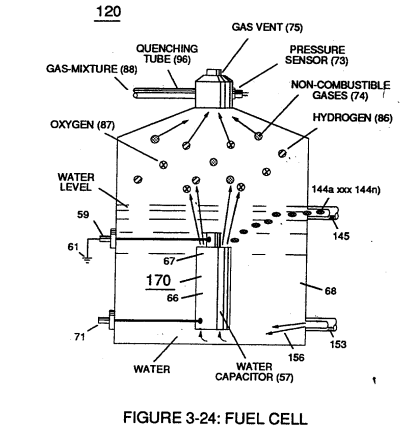
To further prevent voltage fluctuation during resonant action, Phase Lock Loop technique of Pulse Indicator circuit (110) is utilized during pulsing operations.
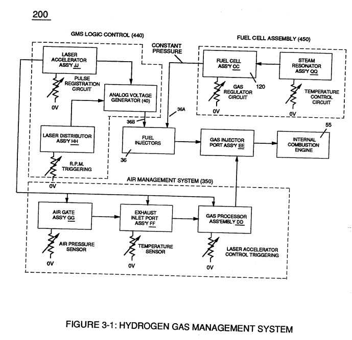
The resultant fuel-gas (88) is, now, transferred through Quenching Tube (96) of Figure (3-41) to, through and beyond Fuel Injectors (36) of Figure (3-1) for Hydrogen gas utilization.
 In cases where applied voltage amplitude is to remain constant while promoting Resonant Action during control-state, incoming pulse train (64a xxx 64n) is varied independent of voltage amplitude to attenuate voltage intensity (66/67) which, in turn, effects gas production.
In other applications, Voltage amplitude (66/67) in direct relationship to pulse-train (64a xxx 64n) may be varied together in a progressive manner to further control gas production. Or pulse-train (64a xxx 64n) can remain constant while voltage amplitude is varied.
In all cases, Resonant Action is being promoted to produce hydrogen gas on demand.
In terms of Longevity, voltage zones (E1/E2) are composed of or made of stainless steel T304 material which is chemically inert to hydrogen, oxygen, and ambient air gases (dissolved gases in water) being liberated from water bath (68) during voltage stimulation (65).
Under actual certified laboratory testing stainless steel T304 life expectancy (material decomposition) is .0001 per year since voltage (65) is a physical force, setting up a non-chemical environment since amps consumption is being restricted to a minimum and "no" electrolyte is added to water bath (68).
In practice, stainless steel voltage plates (E1/E2) physically forms voltage zones (66/67) regardless of geometric shape or configuration of resonant cavity (170).
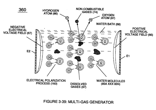
Under normal gas ignition or gas combustion process, released Fuel-Gases (88) of Figure (3-39) as to Figure (3-24) nets a thermal explosive energy yield (gtnt) of approximately 2 1/2 rimes greater than gasoline.
|
Figure (3-39)
|
Figure (3-24) |