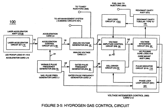
Voltage Amplitude Control Circuit (50)
Voltage amplitude control circuit (50) of Figure (3-5) performs several functions simultaneously:
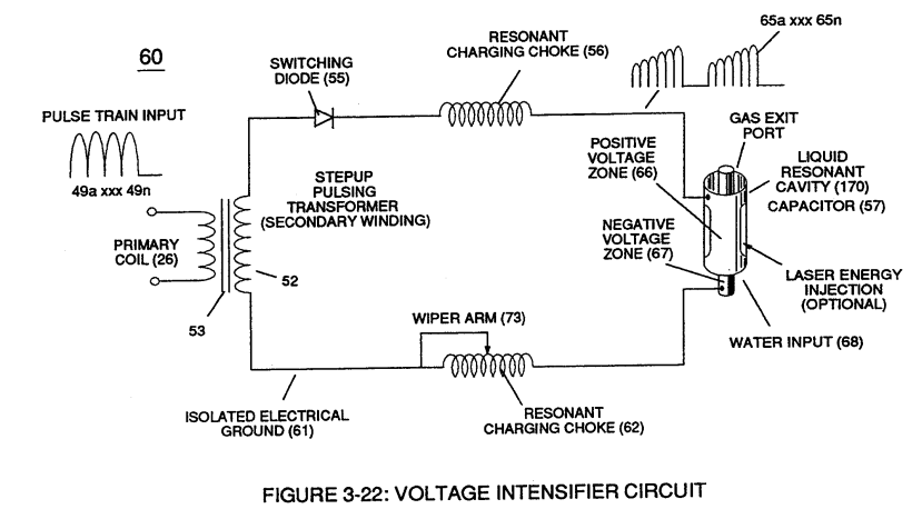
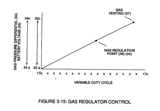
First, regulates car battery electrical voltage potential (32) of Figure (3-15) being applied to primary coil (26) of Figure (3-21); and secondly, regulates gas pressure of Fuel Cell (120) of Figure (3-22), as graphically depicted in Figure (3-15).
|
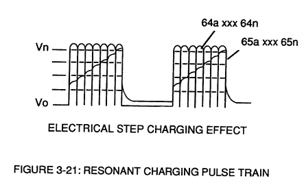
Figure (3-21)
|
Figure (3-22)
|
 Each regulatory stage (27) and (28) works separately and independent of each other but are! electronically linked or coupled together to produce a common analog signal (32) having a predetermined voltage level (32a xxx), as further shown in Figure (3-15).
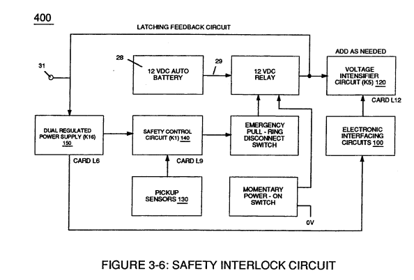
Regulator stage (27) of circuit (50) converts battery voltage potential (29) of Figure (3-6) via electrical terminal (31) of Figure (3-5) as to Figure (3-6) into a analog voltage signal (32) of Figure (3-15) which corresponds to but is electrically isolated (crossover voltage from two separate power supplies) from incoming gas volume signal (23) of Figure (3-14), as shown in Figure (35).
Variable voltage range (32a xxx 32n) from one (1) up to twelve (12) volts (regulating battery voltage) is applied across primary coil (26) of Voltage Intensifier Circuit (60) of Figure (3-21).
Second regulator stage (28) simply acts and function as a gas regulator (33) by preventing Fuel Gas production beyond a predetermined gas pressure level (34) of Figure (3-15) during Fuel Cell operations and, as such, maintains constant gas pressure to Fuel Injectors (36) of Figure (3-1) regardless of engine performance (R.P.M. response).
If for example, Fuel Gas production is greater than demand, then, analog signal (32) is reduced to proper voltage level (35) (voltage level directly determines gas pressure via Resonant Action) required to maintain gas pressure (34).
Conversely, analog signal (32) is always allowed to exceed voltage level (35) during injection (36) of Figure (3-1) until gas-point (34) is reached.
In cases where linear voltage (32) drops (descending value) below gas-point (35) then gas regulator stage (28) increases voltage amplitude (32a xxx 32n) (analog voltage) to voltage point (35).
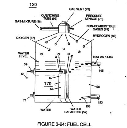
If gas pressure (34a xx) should exceed gas point (35) during injector off-time, gas pressure release valve (75) of Figure (3-24) (gas venting 37 of Figure 3-15) expels Fuel gases (88) until gas point (34) is either reached or a delay timing circuit activates Safety Control Circuit (14) of Figure (3-6) which, in turns, switches off or disconnects applied electrical power (28) to Fuel Cell electrical system (400) of Figure (3-6).
|
Figure (3-15)
|
Figure (3-6)
|
Gas logic circuit (310) of Figure (3-5) supplies logic function to Voltage amplitude control circuit (50) to maintain proper gas pressure to gas injector (36) of Figure (3-1) by electronically monitoring achieved gas pressure via pressure sensor (73) of Figure (3-24).
|
Figure (3-1)
|
Figure (3-24)
|
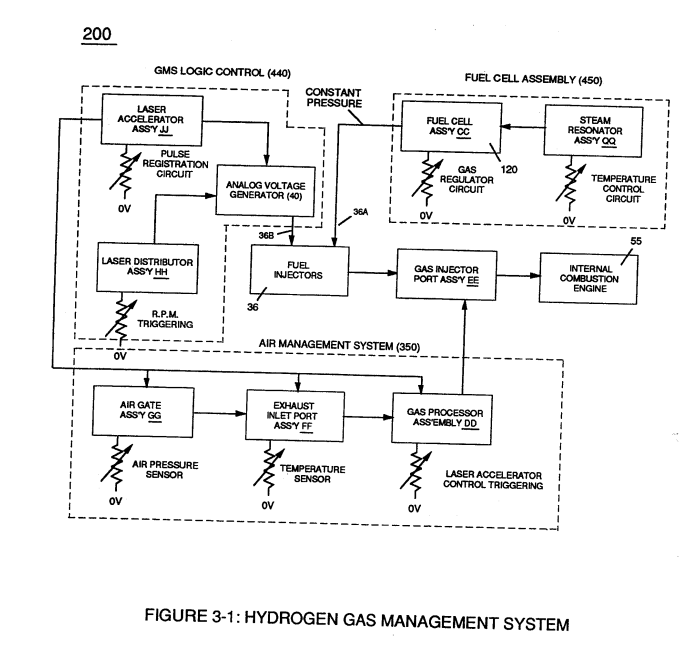
In terms of operability, Laser Accelerator Assembly (20) of Figure (3-5) is, now, attenuating battery voltage potential (32a xxx 32n) which is electrically connected to Voltage Intensifier Circuit (60) of Figure (3-5).