Transformer Action
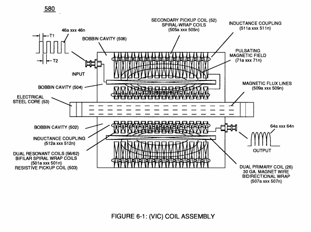
Inductance Core (53) of Figure (6-1) composed of "Grain Oriented" Electrical Steel laminations step up applied Voltage (49) when Magnetic Field Coupling (71) of Figure (7-8) cross over to Secondary Pickup Coil-winding (52) which has more turns of wire than Primary Coil- winding (26) by way of "Eddy" currents that induce magnetic flux lines of forces (71a xxx 71n) emanating away from magnetic core material (53) and caused by Primary Coil (26) being electrically energized during pulsing operations (T1a xx T1n), as illustrated in (690) of Figure (7-8).
|
(53) of Figure (6-1)
|
(71) of Figure (7-8)
|
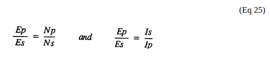
Magnetic Induction (71a - 71n) is determined by Inductance Permeability (μL) of core material (53) along with VIC circuit geometry ability to step up Voltage Potential (Vo - Vn) by way of "Transformer Action", and is expressed in the following equations:
Where,
 (Ep) is voltage induced in Primary Coil (26),
(Es) is Voltage induced in Secondary Coil (52),
(Np) is the number of turns of wire that make up Primary Coil-Wrap (504) of Figure (6-1),
(Ns) is the number of turns of wire that make up Secondary Coil-Wrap (505) of Figure (6-1),
(Is) is the established current flow (under load) in Secondary Coil-Winding (52) ,
(Ip) is the amount of current flow in the Primary Coil-Winding (26) when electrically "energized" during pulsing operations (49a xxx 49n - T3 - 49a xxx 49a).
The turns ratio of the VIC Transformer (26/52) is determined by the following equation:
Where,
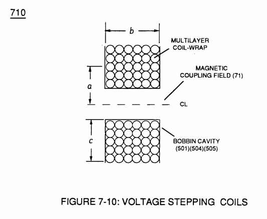
(Ns) is the number of turns of wire for each bobbin cavity (505) of Figure (6-1) as to (710) of Figure (7-10) that are electrically connected in series arrangement (505a xxx 505n) to form Secondary Coil-Wrap (52),
|
(505) of Figure (6-1)
|
(710) of Figure (7-10)
|
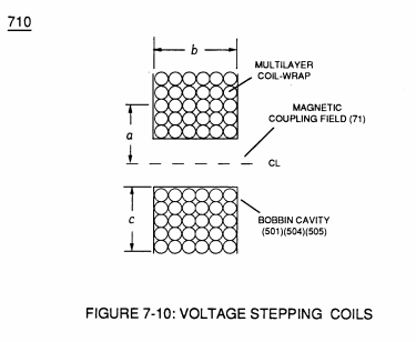
(Np) is the number of turns of the Primary Coil (26) wire-wrapped about spool cavity (504)
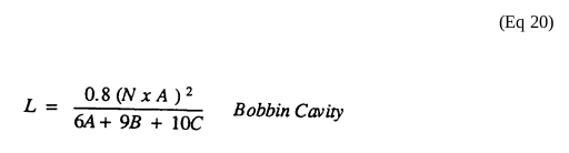 ... each bobbin cavity adhering to equation (Eq 20), as illustrated in (710) of Figure (7-10).
|
(505) of Figure (6-1) |
(710) of Figure (7-10)
|
The impedance ratio of VIC transformer is determined by:
Where,
(1'2) is the sum of the magnetic field strength (FL4) of the primary coil (26) and the induced magnetic field (FL3) of the Secondary Pickup Coil (52) during each pulse cycle (T1) in direct relationship to repetitive pulse cycling (T1a xxx T1n) and both magnetic fields (FL3/FL4) interacting, and is expressed in the following equation:
Where,
(M) is the mutual inductance expressed in the same units .as (La),
(La) is the total inductance of Primary coil (26) and Secondary coil (52) with fields aiding Coupling Inductance (Rp) between the Primary coil (26) and Secondary Coil (52) is further extrapolated in the following equation:
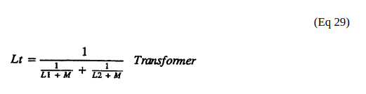
Where,
(Lt) is the total inductance,
(L1) and L2) are the inductances of each individual transformer coils (26)(52),
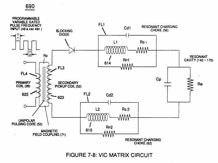
(M) is the mutual inductance of each transformer coil (26/52) being in parallel relationship with fields aiding Coupling Inductance (Rp1) and (Rp2) in (690) of Figure (7-8) is further expressed in the following equation:
Where,
(Lt cc) is the total inductance of Choke Coils (FL1 - FL2),
(L1) and (L2) are the inductances of each individual choke coil (56)(62) in series with Secondary Coil (52) Electrical Voltage
Potential (700) of Figure (7-9) and being exposed to the same Voltage Transformer (26 - 53 - 52) magnetic field (Rp) with aiding fields,
(M) is the mutual inductance of choke coils (L1/L2) since Transformer Magnetic Field (Rp) is the excitation External Magnetic Field (Rp1/Rp2) by way of Unipolar Pulsing Core (53).
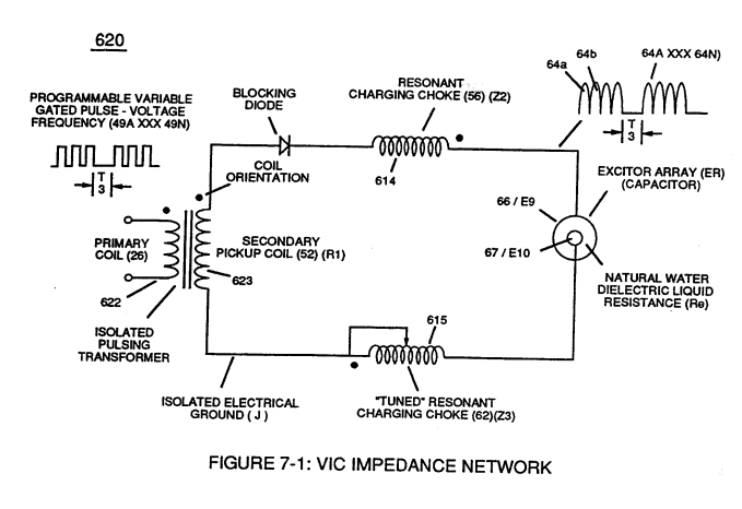
VIC Coil Assembly (580) of Figure (6-1) as to (690) of Figure (7-8) in reference to Schematic Circuit (620) of Figure (7-1) is constructed in such a way as to rotate and position Inductor Coils (26 - 52 - 56 - 62) to be of the same electromagnetic polarity orientation, indicator mark (e)
|
(580) of Figure (6-1)
|
(690) of Figure (7-8)
|
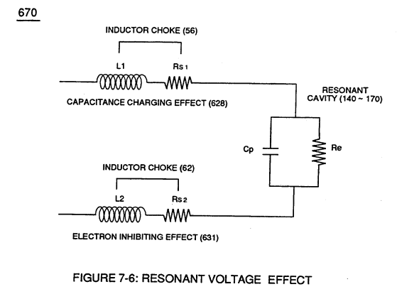
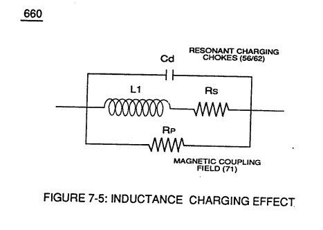
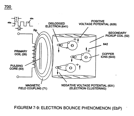
... thus, allowing Inductance Fields (FL1 - FL2 - FL3 - FL4) to be aiding one another during the same sequence of pulse-time (T1) ... thereby, allowing Inductance Charging Effect (660) of Figure (7-5) and Resonant Voltage Effect (670) of Figure (7-6) to interact with the dielectric properties of water (Re) to cause and inhibit electron flow (IF) since "electrons" magnetic field (547) of Figure (5-9) locks onto the electromagnetic fields of each energized choke coils (FL1/FL2) during Voltage Excitation (Vo -Vn) which, now, brings on and allows "Electron Bounce Phenomenon" (700) of Figure (7-9) to take place.
|
Inductance Charging Effect (660) of Figure (7-5)
|
Resonant Voltage Effect (670) of Figure (7-6)
|
|
(547) of Figure (5-9)
|
(700) of Figure (7-9)
|


(See Appendix B Note 1)
Note 1) The Electron Inhibiting Effect (631) of Figure (7-6) to cause "Electron Clustering" (Grouping/collecting negative charged particles at a given point) (700) of Figure (7-9) to produce ''Negative Voltage Potential" ( B- ) at one side of Water Gap (Cp) of Figure (7-8) is accomplished by low electrical power input (Tab 38) when Choke-Coil (62) of Figure (7-1) magnetic field (FL2) (690) of Figure (7-8) during pulse on-time (49) impede "Electron-Flow" since electron mass is composed of electromagnetic matter which interacts with magnetic field strength (FL2).
Capacitance Charging Effect (628) prevents amp influxing away from Water Gap (Cp) in a similar manner
... producing "Electrical Stress" (SS' - RR') (B+/B-) across Water Gap (Cp) since both Choke-Coils (56/62) conduct voltage potential (Negative or Positive) during pulsing operations.
|
Electron Inhibiting Effect (631) of Figure (7-6)
|
"Electron Clustering" (Grouping/collecting negative charged particles at a given point) (700) of Figure (7-9)
|
|
''Negative Voltage Potential" ( B- ) at one side of Water Gap (Cp) of Figure (7-8) & magnetic field (FL2) (690) of Figure (7-8) |
Choke-Coil (62) of Figure (7-1)
|