
Water Fuel Injection System - Page 2
To ensure proper energy-flame projection and subsequent energy-flame stability, constant displacement water pump (170) causes and allows ionized ambient air gases (46), noncombustible gases (45), and water (47) to be displaced under static pressure up to and beyond 125 lbs psi, respectively.
 Energy-Flame density is enhanced and sustained by causing ionized gases (46a xxx 46n) of spray port (42) to be deflected into liquid spray path (41), together water mist (47) and ionized air gas (46) are, now, directed toward and deflected through non-combustible gas spray path (43)
... producing uniformed water-fuel mixture (48), as illustrated in Figure (4-5).
Energy-Flame temperature is regulated by controlling the volume flow-rate of each fluid-mediums (47 / 45 / 46) in direct relationship to applied voltage intensity (33 / 36), as further illustrated in Figure (4-2) as to Figure (4-5).
|
Figure (4-2)
|
To elevate Energy-flame-temperature still further, simply increase fluid-displacement (46/47) while maintaining or reducing the volume flow rate of non-combustible gases (45) during an increase of applied voltage amplitude (V0 xxx Vo) of Figure (4-2) as to Voltage Intensifier Circuit (110) of Figure (4-9) and Electron Extraction Circuit (120) of Figure (4-10).
|
Figure (4-9)
|
Figure (4-10)
|
To lower Energy-flame temperature simply increase the amount of non-combustible gases (45a xxx) or reduced the fluid flow rate (45 / 46 / 47) uniformly while lowering pulse voltage amplitude (xxx V0).
To establish a predetermined or given Energy-flame temperature adjust fluid-medium (45 / 46 / 47) and applied voltage amplitude (V0 xxx) independent of each other to obtain the desired results.
The resultant energy-flame pattern is further maintained by allowing the ignited, compressed, and moving gases (29) of Figure (4-5) to be projected to, pass through and beyond nozzle-port (32) under pressure due to gas expansion caused by thermal gas ignition.

Voltage Igniter Stage (180) of Figure (4-5) as to Voltage Intensifier Circuit (110) Figure (4-9) as to Extraction Circuit (10) of Figure (4-10) performs several functions simultaneously to initiate and trigger thermal explosive energy-yield (gtnt) (16) beyond normal gas burning levels:
|
Figure (4-9)
|
Figure (4-10)
|
Water droplets (28a xxx 28n) escaping from spray-mist (47) and exposed to high intensity voltage fields of opposite polarity 33/36) are stimulated to undergo Electrical Polarization Process (160) of Figure (3-26)
|
Figure (3-26)
|
Figure (3-30)
|
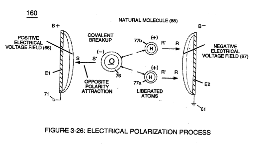
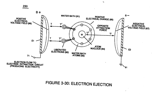
... which not only separates and splits the unlike atoms of the water molecule but also causes the unlike atoms (hydrogen atoms 77a /77b and oxygen atom 76) to experience electron ejection (230) of Figure (3-30) as to (71) of Figure (4-10) since voltage intensifier circuit (110) of Figure (4-9) inhibits and prevents electron flow to enter into gas ignition process (180), as further illustrated in Figure (4-8).
|
Figure (4-8)
|
Figure (4-10)
Figure (4-9)
|
