Tri - Coil Construction
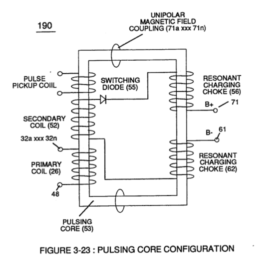 Resonant Choke Coils (56/62) of Figure (3-23) (Memo WFC 422 DA) are composed of 430F or 430FR inductance stainless steel film coated (hi dielectric value) wire (typically .004 Ga. or smaller) which are axially (spiralled) Bifilar wound about core bobbin (502), forming individual spiral-wrap (inner to outer circumference and being equally-length) coils (501a xxx 501n) electrically connected in sequential order to form resistive pickup coil (503).
Primary Coil (26) (typically .030 Ga.) film coated magnet wire is longitudinal wrapped in space relationship on top of and layered bidirectional (507a xxx 507n) across spiral-wrap coils (501a xxx 50 In) to complete bobbin cavity (504).
Secondary pickup coil (52) of Figure (3-23) is, also, composed of individual spiral wrapped coils (505a xxx 505n) (typically .002 Ga. magnet wire) electrically connected in sequential order to form bobbin cavity (506) which is placed on top of and in space relationship to primary coil cavity (504).
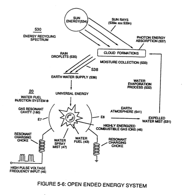
Resonant bobbin assembly (503), primary bobbin assembly (504), and secondary bobbin assembly (506), now, make up and structurally forms voltage intensifier (VIC) coil-assembly (530) of Figure (5-6) when electrical steel core material (53) forms a close-loop magnetic induction pathway centrally through and around (VIC) coil-assembly (530), as schematically illustrated in (190) of Figure (3-23) (Memo WFC 422 DA).
|
(VIC) coil-assembly (530) of Figure (5-6)
|
(190) of Figure (3-23)
|