Electron Bounce Phenomenon
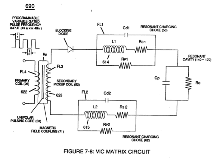
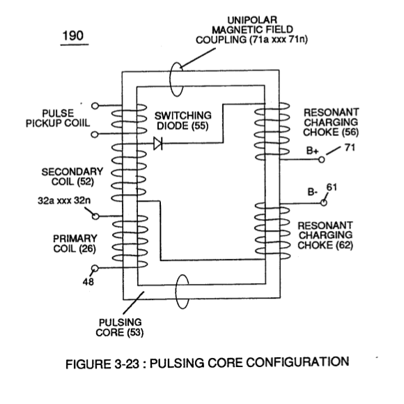 High Voltage Potential of Difference (Vo - Vn) (SS' - 617 -RR') is accomplished when magnetic flux lines of force (71a xx 71n) (Rp) emanating away from closed-loop magnetic pulsing core (53) of Figure (190) penetrates Inductance coil-windings (52 - 56 - 62) simultaneously during each and every pulse on-time (T1a xxx T1n) as programmable pulse-train (49a xxx 49n T3 - 49a xxx 49n) is adjusted to "Tune - in" to the dielectric property of Water (Re)
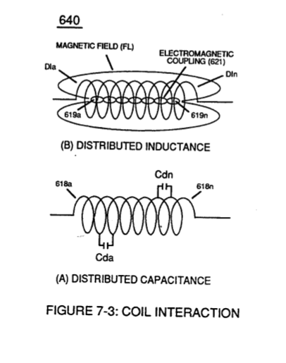
.... causing mutual inductance (μ1) (see equations Eq 28 thru Eq 30) to transform Distributed Capacitance (Cda xxx Cdn) of Figure (7-3) of each inductance coils (52 - 56 - 62) into a coherent Voltage Potential (Yo •..• Vn) equaling the sum of Voltage Potential (Vp) developed across each Pickup Coils (VpT + Vp1 + Vp2)
|
Distributed Capacitance (Cda xxx Cdn) of Figure (7-3) |
equations Eq 28 thru Eq 30 Where, (M) is the mutual inductance expressed in the same units as (La), (La) is the total inductance of
Coupling Inductance (Rp) between the Primary coil (26) and Secondary Coil (52) is further extrapolated in the following equation: Where, (Lt) is the total inductance, (L1) and L2) are the inductance of each individual transformer coils (26)(52), (M) is the mutual inductance of each transformer coil (26/52) being in parallel relationship with fields aiding.
Coupling Inductance (Rp1) and (Rp2) in (690) of Figure (7-8) is further expressed in the
|
... producing Dynamic Voltage Potential (600) of Figure (6-3) during repetitive pulsing (49a xxx 49n - T3 - 49a xxx 49n)
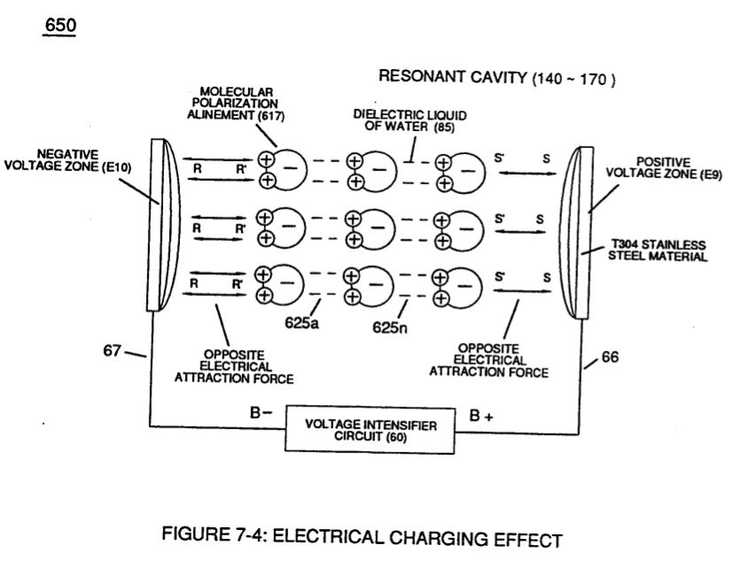
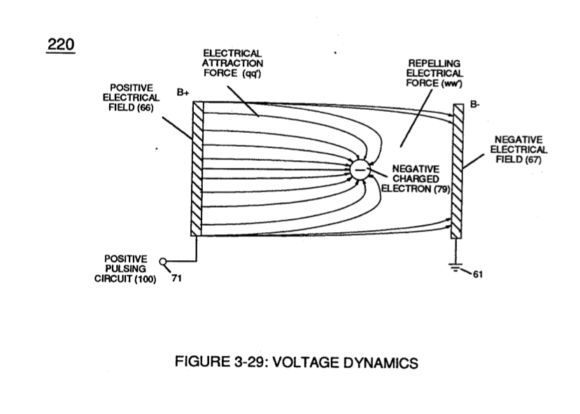
... setting up and performing pulsating Opposite Electrical Attraction Force (SS' ~ 617 ~ RR' - T3 - SS' ~ 617 - RR') of Figure (7-4) as to Voltage Dynamics (220) of Figure (3-29)
|
Opposite Electrical Attraction Force (SS' ~ 617 ~ RR' - T3 - SS' ~ 617 - RR') of Figure (7-4)
|
Voltage Dynamics (220) of Figure (3-29)
|
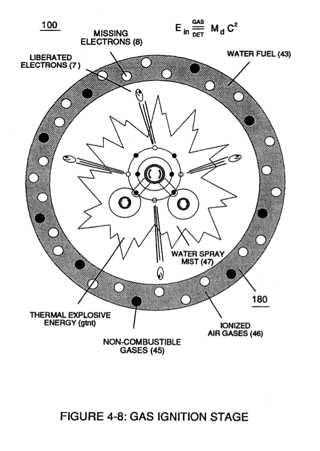
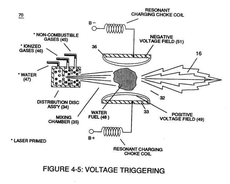
... triggering Hydrogen Fracturing Process (90) of Figure (5-5) as to (100) of Figure (4-8) ... instantly releasing thermal explosive energy (gtnt) (16) from Water (85) on demand, as illustrated in Taper Resonant Cavity (590) of Figure (6-2) as to (70) of Figure (4-5).
|
Hydrogen Fracturing Process (90) of Figure (5-5) |
(100) of Figure (4-8)
|
|
Taper Resonant Cavity (590) of Figure (6-2)
|
(70) of Figure (4-5)
|

The resultant Dynamic Voltage Potential of Difference (opposite electrical attraction force) (SS' - 617 •... RR') is in balance phase of equal electrical intensity (66 = 67) of opposite polarity (positive electrical voltage potential _66 equals negative electrical Voltage potential 66 since the Voltage Coefficient of Inductance (FL1/FL2), Voltage Coefficient of Capacitance (Cd1/Cd2), and Voltage Coefficient of Resistance (Rs1/Rs2) across choke coils (L1/L2) are the same values
... allowing, Voltage Bounce Phenomenon (700) of Figure (7-9) to be preformed.
|
(700) of Figure (7-9)
|
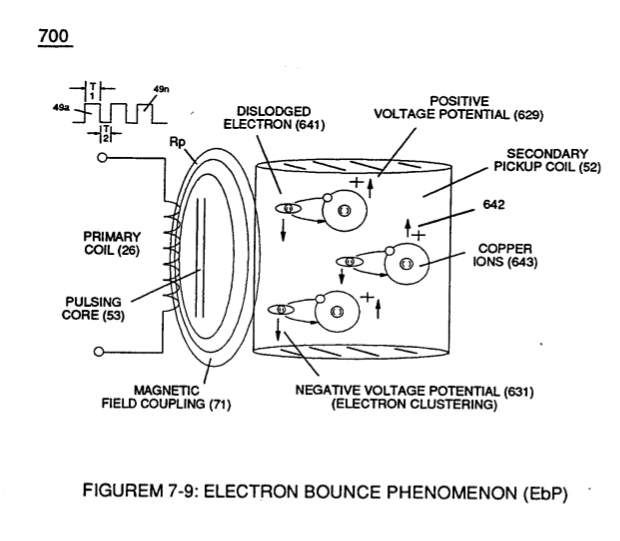
Magnetic Field Coupling (71) of Figure (7-9) entering into and passing through Secondary Coil-winding (52) of Figure (7-8) causes and produces copper ions (643a xxx 643n) (Positive Charged atoms 542a xxx 542n having missing electrons) when moving external electromagnetic field strength (71a xxx 71n) is sufficient enough to dislodge electromagnetically charged electrons (641a xxx 641n) from copper atoms making up copper wire material (52).
|
(52) of Figure (7-8)
|
Collectively, the resultant positive electrical charged copper ions (642a xxx 642n) added together produces Positive Voltage Potential (629) being electrically applied to choke-coil (56);
whereas, the "Liberated" negative electrical charged electrons (641a xxx 641n) added together provides Negative Voltage Potential (631) to the opposite end of Secondary Wire (52) being electrically connected to choke coil (62).
Once Secondary Coil-winding (52) is de-energized by the removal (collapsing magnetic field during pulse off-time T2 of external Magnetic Field (71), the dislodged electrons (641a xx 641n) return to positive charged copper ions (642a xx 642n)
... terminating and switching off opposite voltage potential (629 - 631) when positive electrical state of the copper atoms changes back to net electrical charge of zero.
Sustaining and maintaining the resultant induced Voltage Potential (Vo - Vn) without "Electron Discharged" (inhibiting electron flow) through Choke Coil (62) while, at the same time, inhibiting (preventing) any additional or other electrons from entering into Secondary copper wire-zone (52) by way of Choke Coil (56) is herein called "Electron Bounce Phenomenon" (EbP), as illustrated in (700) of Figure (7-9).
|
(700) of Figure (7-9)
|
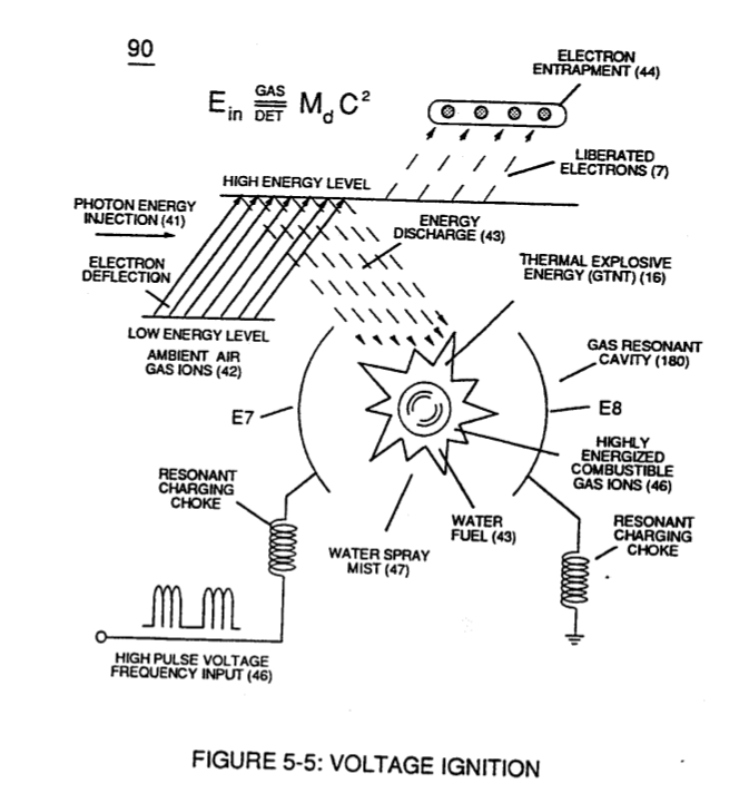 Electrically Interlinked serially together, Electron Bounce Phenomenon (EbP), Voltage Coefficient of Inductance (F11/F12), Voltage Coefficient of Capacitance (Cd1/Cd2), Voltage Coefficient of Resistance (Rs1/Rs2), and Dielectric Coefficient of Water resistance (Re) allows Voltage Potential (Vo - Vn) of opposite electrical polarity to perform work (SS' _ 617 _ RR') without amp influxing, thus, not allowing the introduction of electron flow into Hydrogen Fracturing Process (90) of Figure (5-5) during Voltage Stimulation (SS' - 617 _ RR')
... causing "electron clustering" (641a xxx 641n) to take place within Copper Wire Zone (52) during pulse on- time (T1)
... inhibiting "electron flow" to maintain opposite voltage potential (66/E9 _ 67/E10) across Resonant Water Gap (616) during the process of converting water-fuel (85) into instant thermal explosive energy (gtnt)
... therefore, producing a physical force-yield (Fy) during gas-ignition (70) of Figure (4-5) which is directly related to the liquid volume of water (85) per injection cycle and applied Resonant Voltage Intensity (Yo -Vn), as illustrated in (590) of Figure (6-2) as to (90) of Figure (5-5).
|
physical force-yield (Fy) during gas-ignition (70) of Figure (4-5)
|
(590) of Figure (6-2)
|
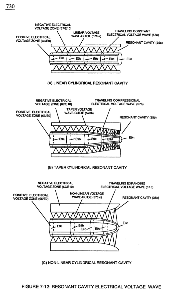
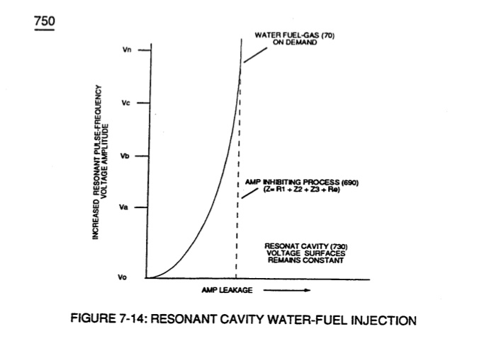
Of course, in practical terms of component interaction, a minute amount of amp leakage is present and does occur due to Electronic Component Limitations but is negligible as to the overall performance of the Hydrogen Fracturing Process (590) of Figure (6-2) when being subjected to either one of Traveling Electrical Voltage Wave-forms (730 a-b-c) of Figure (7-12), see Voltage Graph (750) of Figure (7-14) once again.
|
Traveling Electrical Voltage Wave-forms (730a - b - c) of Figure (7-12)
|
Voltage Graph (750) of Figure (7-14)
|