8-6 - VIC Voltage Sync-Pulse Circuit
Voltage Sync-Pulse Gated Frequency (583/602a xxx 583/602n) (603/604a xxx 603/604n) of Figure (8-1) as to (605/606a xxx 605/606n) (607/608a xxx 607/608n) (609/611a xxx 609/611n) of Figure (8-2)
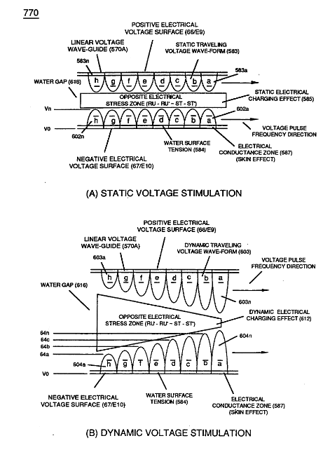
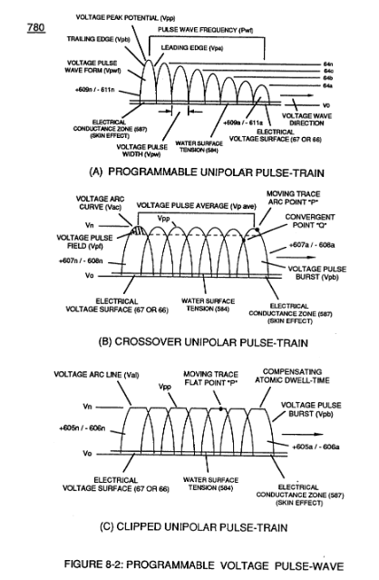
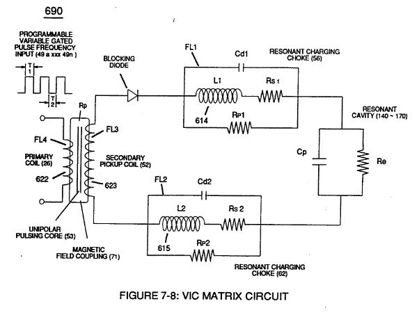
... all, forming Voltage Pulse Burst Wave (619) as to Unipolar Pulse-Train (780A), Crossover Unipolar Pulse-Train (780B), and Clipped Unipolar Pulse Train (780C) as to Traveling Voltage Wave-Action (770) of Figure (8-1) of opposite voltage polarity (+/-) of equal Voltage-Pulse Amplitudes (+Vpp/- Vpp) are zero reference to electrical ground state (0V) by placing Amp Inhibitor Circuit (860) (Amp Inhibiting Coil 617, Blocking Diode 618, and Magnetic Induction Core 619) between electrical ground (0V) and Center Tap of Dual Bifilar Secondary Pickup Coils (616A/B) of VIC Matrix Circuit (690) of Figure (7-8) as to VIC Impedance Network Circuit (620) of Figure (7-1) , as illustrated in (840) of Figure (8-10).
 |
 |
|
(620) of Figure (7-1)
|
(690) of Figure (7-8) |
(840) of Figure (8-10)
|

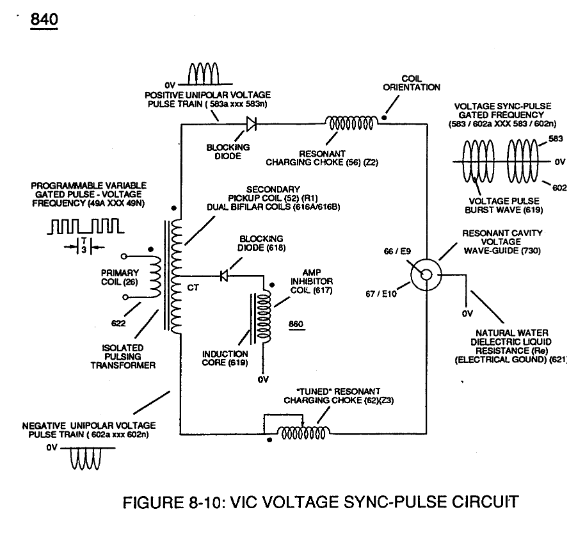
By doing so, Balance Phasing of opposite voltage intensity (+Vpp / - Vpp) is accomplished without experiencing current influxing caused by differential variances where Negative Voltage Peak Potential (-Vpp) is less than Positive Voltage Peak Potential (+Vpp) or Vise Versa ... allowing Inductor Resonant Choke Coils Electromagnetic Fields Intensity (+Z2 / -Z3) to be, in turn, free of Electromagnetic variances of intensity (Z2 - Z3).
This non-voltage shift (Balanced Phasing of opposite Voltage Potential) helps prevents atom displacement during "Snapping-Action" by which "Resonant Electrical Stress" of opposite electrical polarity (RU/RU' - ST/ST') is applied equally across Water Molecule (s) (85) to propagate either Static (585) or Dynamic (612) Electrical Charging Effect (s) at elevated Voltage Peak Potential (s).
 Amp Inhibiting Coil-Assembly (617) is made up of magnetic inductance Stainless Steel 430FR wire material wrapped around a closed-loop Induction Magnetic Core (619) which is a separate coil-unit (860) apart from VIC Coil Assembly (580) of Figure (6-1).
Blocking Diode (618) functions as an "Electrical Isolator" that prevents electrical discharge of Dual Secondary Coil (616A / B) during applied Pulsing Operations (49a xxx 49n).
To ensure and maintain Capacitance Charging Effect (650) of Figure (7-4) across Water-Gap (Cp) of (7-8) during applied pulsing operations (49a xxx 49n), Crossover Voltage Wave-Form (780B) as to (780C) of Figure (8-2) is generally utilized by not allowing Convergent Point "Q" of Figure (780B) to reach Electrical Ground Point (0V) when each Unipolar Voltage Pulse (Vpp) is electrical energized in phase-distance relationship to cause the trailing edge (Vpb) of the first Voltage-Pulse (Vppl) to meet the uprising leading edge (Vpa) of the second Voltage Pulse Wave (Vpp2) at a distance above ground state (OV) determined by the Space-movement of the reforming Voltage Peak Wave (Vppa xxx Vppn) within Voltage Pulse Width (TI), as illustrated in Rotary Crossover Voltage Sync-Pulse Circuit (850) of Figure (8-11) where each VIC Pickup Coils (52A-52B -52C) are axially spaced 120· apart to cause Convergent Point "Q" to be located 1/3 the height of Voltage Amplitude Peak Level (Vpp), as an example.
|
(650) of Figure (7-4)
|
(Cp) of (7-8)
|
|
Convergent Point "Q" of Figure (780B)
|
Rotary Crossover Voltage Sync-Pulse Circuit (850) of Figure (8-11)
|