Water Fuel Injector (Taper Resonant Cavity Chamber)
Taper Resonant Cavity Chamber
To set up, trigger, and perform Hydrogen Fracturing Process (390) of Figure (3-42) (see WFC Memo 422 DA) gas ignition stage (100) of Figure (6) ...
(390) of Figure (3-42) |
(100) of Figure (6)
|
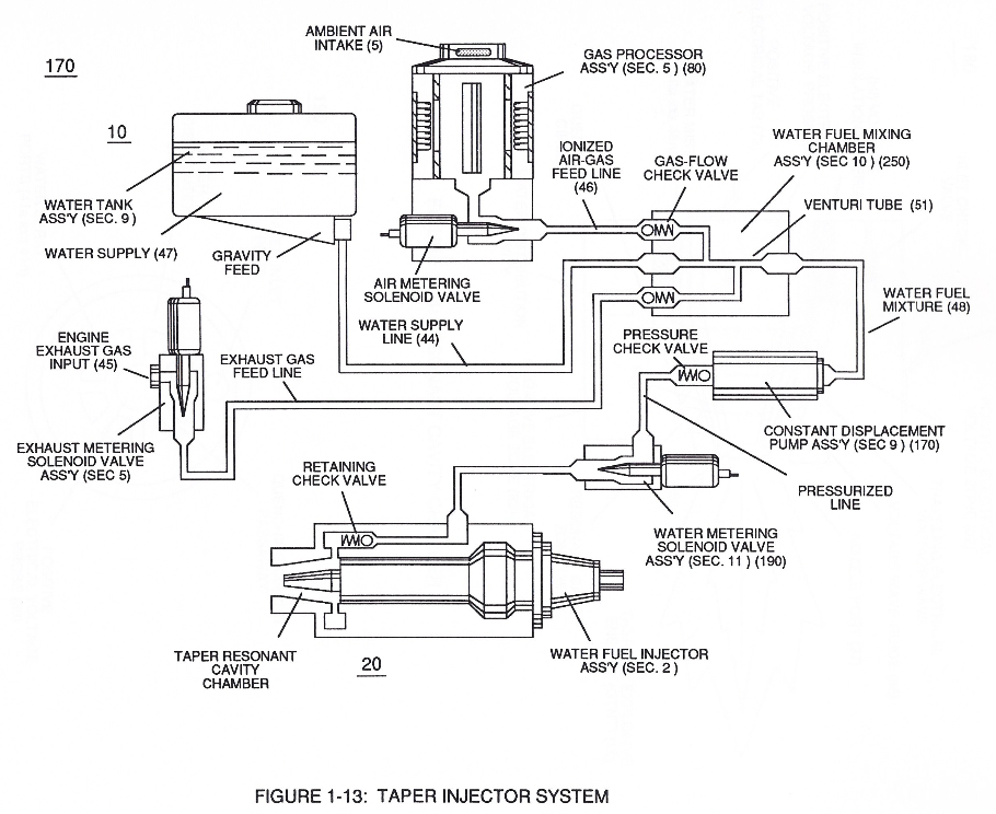
releasing thermal explosive energy (gtnt) via flame projection (16) of Figure (3B) as to Figure (14), Water Fuel Injection System (10) of Figure (1) as to (170) of Figure (13) incorporates and uses Taper Resonant Cavity Chamber (180) of Figure (14) to enhance operational parameters of Hydrogen Fracturing Process (100) of Figure (6) being stimulated to activation by opposite electrical voltage fields (49/51) of Figure (3B) as to (180) of Figure (14).
|
flame projection (16) of Figure (3B)
|
Water Fuel Injection System
|
(170) of Figure (13) |
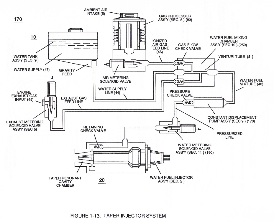 In like manner, water supply (10) of Figure (170), non-combustible gases (45) (Engine Exhaust gases), and ambient air ionized gases (46) (air gases having missing electrons) are uniformly intermixed when moving into, passing through and beyond fluid mixing chamber (250) of Figure (13) by way of venturi tube-cavity (51)...
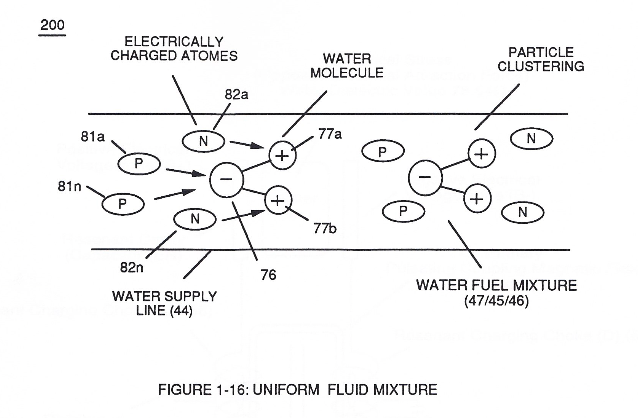
allowing water fuel mixture (47/45/46) (48) to be particle aligned by opposite electrostatically charged atoms
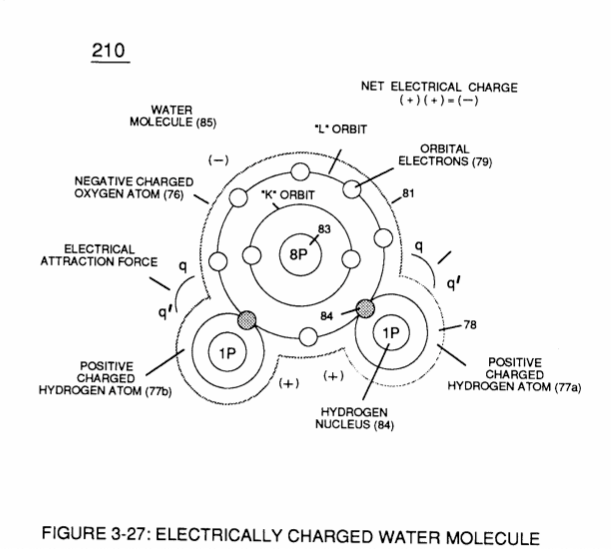
...positive charged gas particles (81a xxx 81n) being directed to and attached to negative charged oxygen atom (76) of water molecule (47);
while, during the same interim period of time, negative charged gas particles (82a xxx 82n) being directed onward to and affix themselves to positive charged hydrogen atoms (77a / 77b), as illustrated in (200) of Figure (16).
The resultant water fuel-mixture (48) is, now, pressurized up to and beyond 125 lbs of fluid-pressure by Fluid Displacement Pump (170) of Figure (13), as before, to cause and form water fuel-droplets (48a xxx 48n) when water fuel (48) enters into, passes through and beyond spray ports (41a xxx 41n) forming Quenching Disc Structure (190) of Figure (15).
|
Fluid Displacement Pump (170) of Figure (13)
|
Quenching Disc Structure (190) of Figure (15)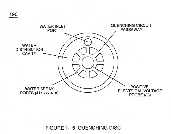 |
The injected water fuel-droplets (48a xxx 48n), now, surrounds outer surface area of exposed positive probe (33) while entering into Taper Resonant Cavity (180), as illustrated in (70) of Figure (3B) as to Figure (14).
|
(70) of Figure (3B)
|
Figure (14)
|
Once water fuel-droplets (xxx 48n) fully occupies open space cavity (Resonant Cavity Zone) (35) and then exposed to applied pulsating opposite electrical voltage fields (49/51) of voltage wave form (280) of Figure (17), the electrically stimulated water fuel droplets (48a xxx 48n) are subjected to release thermal explosive energy (gtnt) (16) undergoing Electrical-Resonant in a sequential manner:
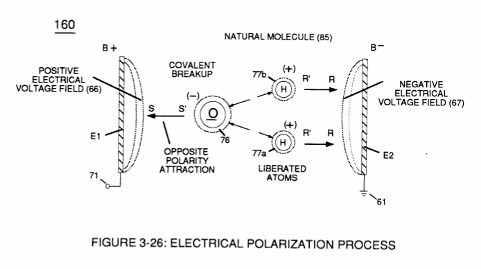
By first, separating water molecule (47) into its component gases (oxygen 76 / hydrogen 77a - 77b) by way of the Electrical Polarization Process (160) of Figure (25) (WFC Memo 422 DA);

secondly, by electrically attenuating the electrical-forces of the newly formed and liberated combustible gases (76, 77a - 77b) via Energy-Priming Process (520) (see WFC Memo 424 titled "Atomic Energy Balance of Water);
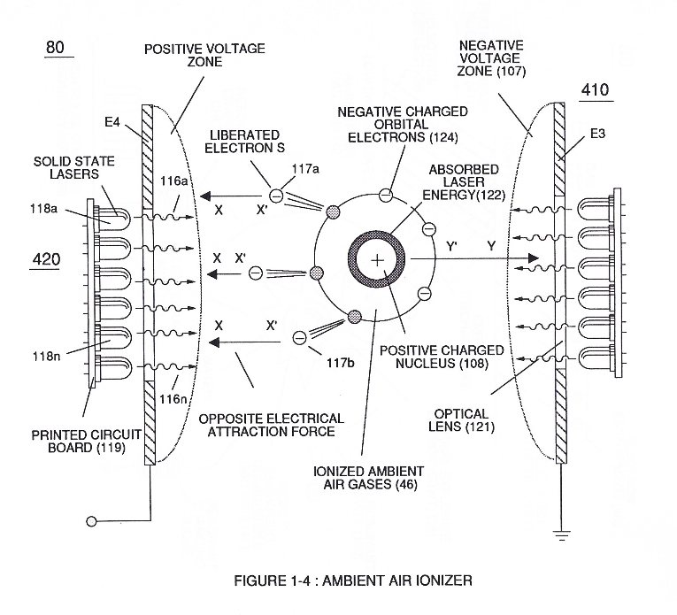
thirdly, by ionizing the released combustible gases by way of Electron Ejection Process (230) of Figure (29) (WFC Memo 422 DA), as further illustrated in (80) of Figure (4);
|
Electron Ejection Process (230) of Figure (29) |
(80) of Figure (4)
|
and finally, spark-ignite the highly destabilized combustible gases (laser primed combustible gases having missing electrons) by electrostatic discharge (kinetic energy agitation), as further exemplified in (280) of Figure (17);
all sequential gas priming functions occurring progressively in an instant of time.
Subsequent and repetitive formation of applied gated electrical voltage pulse-train (210a xxx 210n) of Figure (17) to continued in-flow of water fuel droplets (48a xxx 48n) not only sustains and maintains Hydrogen Fracturing Process (100) of Figure (6) but, also, regulates Thermal Explosive Energy release (16a x 16n) of Figure (14) by attenuating applied voltage amplitude (xxx VL xxx), as graphically shown in Figure (20F) (WFC Memo 420).
|
Hydrogen Fracturing Process (100) of Figure (6)
|
Thermal Explosive Energy release (16a xxx 16n) of Figure (14)
|
This further increase in voltage amplitude (xxxx VL) simply exerts a greater magnitude of opposite Electrical-Stress (SS'-RR') of Figure (25) (TT' - UU') of Figure (29) (WFC Memo 422 DA) across combustible gas atoms (76, 77a - 77b)
|
Figure (25)
|
Figure (29)
|
which, in turns, ejects a greater number of electrons while preventing the formation of the water molecule (390) of Figure (41) (WFC Memo 422 DA) during thermal gas-ignition (180) of Figure (14).
|
(390) of Figure (41) |
(180) of Figure (14)
|

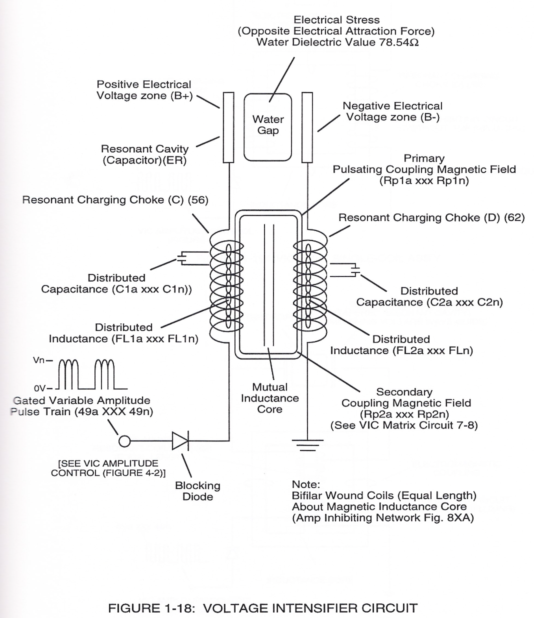
Voltage Intensifier Circuit (220) of Figure (18) allows Electrical-Stress variation (SS' = RR' / TT' = UU') since voltage Intensifier Circuit (220) inhibits electron-flow (amp restriction) into voltage triggering process (210) of Figure (17) as to (100) of Figure (6).
|
voltage triggering process (210) of Figure (17)
|
(100) of Figure (6) |
Electron restriction while varying voltage intensity (Va = Vn) is accomplished by performing several functions simultaneously:
Incoming pulse-train (210a xxx 210n) is adjusted to "tune-in" to the Dielectric Properties of Water (47) which allows Resonant Action (see WFC Memo 424, once again) to occur since the Dielectric property of water (78.54 value) becomes a integral part of Electronic Circuit (110) of Figure (7) as to (220) of Figure (18)
|
Electronic Circuit (110) of Figure (7)
|
(220) of Figure (18)
|
... forming a capacitor (E7 / E8) in series with Resonant Charging Chokes (56/57) placed on opposite sides of Resonant Cavity Zone (35) as to Figure (7) and (8) . . . forming a Resonant Pulsing Circuit (110) of Figure (7) with step-up Pulsing Transformer (33/36), as shown in (220) of Figure (18).
Adjusting Pulse-train (210a xxx 210n) in such a way as to allow pulse off-time (T2) to be synchronized with collapsing and re-formation of electromagnetic field coupling across pulsing transformer (52/53) to produce unipolar pulse frequency (T1a xxx T1n), as illustrated in (220) of Figure (18) as to Figure (17).
|
(220) of Figure (18)
|
Figure (17)
|
Pulse on-time (T1) having a predetermined constant voltage level (xxx VL xxx) is adjusted to maximize transference of electromagnetic energy to Secondary Coil (53) during pulsing operations.
The resultant and newly formed gated Resonant Pulse-train (T1 + T2a xxx T1 + T2n) (58) voltage amplitude (Vo xxx Vn) is, now, attenuated by Sequential Voltage Amplitude Control Circuit (59) once step up Secondary Coil (53) produces a higher voltage level (xxxVL) above incoming pulse-train (210) since Secondary Coil (53) has a greater number of turns of wire.
 |
|
Sequential Switch Circuit (59) simply switches in and out Booster Pickup Coils (61a xxx 61n) in series electrical hookup with Secondary Coil (53) output to elevate voltage intensity across Resonant Charging Chokes (56/57).
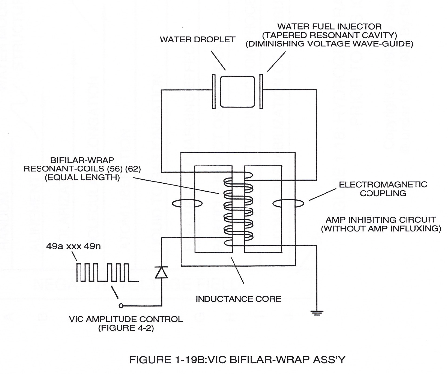
Forming Resonant Charging Chokes (56/57) by using Stainless Steel Electro-Inductance wire-material (430F / T304 or equivalent) which, when electrically pulsed transmits voltage intensity while restricting amp flow during Resonant Pulsing operations. Together, the resistive valve of Stainless Steel wire-coil (56/57) and its inductance generated electromagnetic field (62) of Figure (19) opposes the movement of electrons since the dielectric valve of wire-coils (56/57) inhibits electron exchange while the generated inductance field (62) locks onto the electromagnetic field of the electrons ...generated coil inductance field (62) being greater in electromagnetic... [ends abruptly...]
 |
 |
The Following Page 1-7 was not available
The "Plus Factor" is that induce external electromagnetic field (63/64) across Resonant coil-Tap (67) increases voltage intensity (voltage potential) still further rather than diminishes peak voltage potential due to resistive valve of the stainless steel wire.
In other words, the inductance and capacitance values of stainless steel induction coil (56/57) bypasses voltage drop across its resistive load (ohmic valve of wire).
This induced voltage phenomenon encourages and therefore prevents resonant pulse frequency (58) from being impaired or altered while being electrically transmitted to Resonant Cavity (180) of Figure (14) via electrical tabs (71) and (72) of Figure (14).