CIRCUIT COMPONENT INTERACTION
PULSING TRANSFORMER
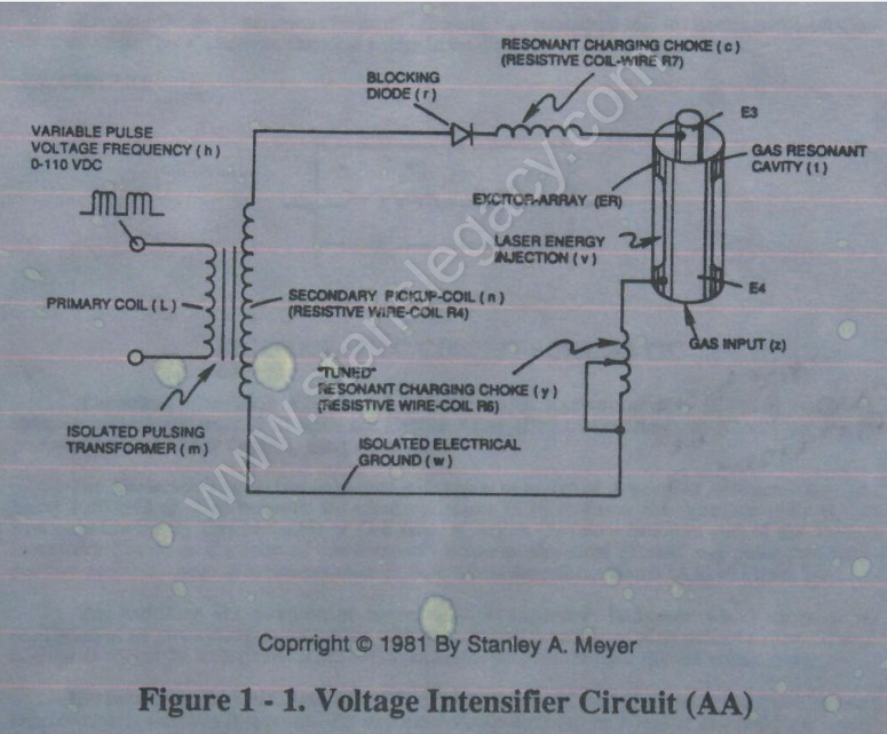
The pulsing transformer (m) steps up voltage amplitude or voltage potential during pulsing operations.
The primary coil is electrically isolated (no electrical connection between primary and secondary coil) to form Voltage Intensifier Circuit (AA).
Voltage amplitude or voltage potential is increased when secondary coil (n) is wrapped with more turns of wire.
Isolated electrical ground (w) prevents electron flow from input circuit ground.
BLOCKING DIODE
Blocking Diode (f) prevents electrical “shorting” to secondary coil (n) during pulse-off time since the diode “only” conducts electrical energy in the direction of the schematic arrow.
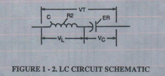
LC CIRCUIT Figure 1-2. LC Circuit Schematic
Resonant Charging Choke (c) in series with Excitor-array (E3/E4) forms an inductor-capacitor circuit (LC) since the Excitor-Array (ER) of Gas Resonant Cavity (t) acts or performs as a capacitor during pulsing operations.
 The Dielectric Properties (insulator to the flow of amps) of Argon Gas (dielectric constant being 1.000545 @ 23°C) between the electrical plates (E3/E4) forms the capacitor (ER) of Gas Resonant Cavity (t).
Gas Molecule or Gas atom of Argon (Ar) now becomes part of the Voltage Intensifier Circuit in the form of “resistance” between electrical ground and pulse-frequency positive-potential... helping to prevent electron flow within the pulsing circuit (AA) of Figure 1-1.
The Inductor (c) takes on-or becomes a Modulator Inductor which steps up an oscillation of an given charging frequency when the effective capacitance of an pulse-forming network in order to charge the voltage zones (E3/E4) to an higher potential beyond applied voltage input.
The Inductance (c) and Capacitance (ER of t) properties of the LC circuit is therefore “tuned” to resonate at a certain frequency.
The Resonant frequency can be raised or lowered by changing the inductance and/or the capacitance values.
The established resonant frequency is, of course, independent of voltage amplitude, as illustrated in Figure 9BB.
The value of the Inductor (c), the value of the capacitor (ER of t), and the pulse-frequency of the voltage being applied across the LC circuit determines the impedance of the LC circuit.
