
Gas Processor
To obtain higher energy-yields beyond the normal gas combustion process, ionized ambient air gases (104) of Figure (3-31) is, now, exposed to and intermixed with Fuel-Gases (88) prior to thermal gas ignition (98) of Figure (3-38), as illustrated in (240) of Figure (3-31).
Figure (3-31)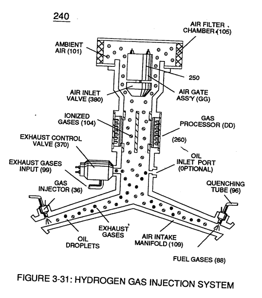 |
Figure (3-38)
|
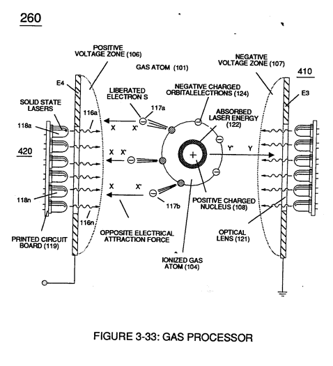 As ambient air gases (101) enters into and passes through air filter chamber (105) toward and beyond air gate assembly (GG), the moving air gases (101) are exposed to high energy voltage fields (up to and beyond 2,000 volts) (106/107) of opposite electrical polarity which causes ambient air gases to become ionized gases (104), as illustrated in (260) of Figure (3-33).
Positive electrical voltage field (106) causes negative charged orbital electrons (124a xxx) to be ejected from gas atom (101) due to opposite electrical attraction force (xx'); while, at the same time, negative electrical voltage field (107) exerts a second electrical attraction force (yy') on gas atom positive charged nucleus (108)
...opposite electrical attraction forces (xx') and (yy') being of equal intensity, as further illustrated in (260) of Figure (3-33).
Once electron ejection occurs, the liberated and free floating electrons (117a xxx 117n) continue to migrate toward positive voltage zone (106); whereas, the newly formed ionized gas atom (having missing electrons) (104) continues to move onward and through air intake manifold (109) of Figure (3-31) to engine cylinder (102) of Figure (3-38).
|
air intake manifold (109) of Figure (3-31)
|
engine cylinder (102) of Figure (3-38)
|
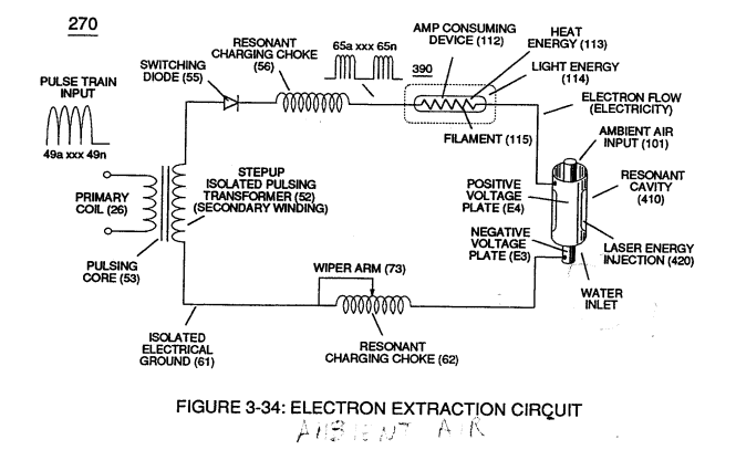
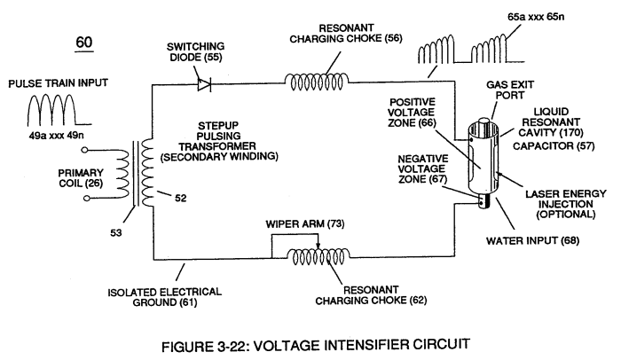
The resultant ionized gas process (260) of Figure (3-33) is performed by Electron Extraction Circuit (270) of Figure (3-34) which function in like manner to Voltage Intensifier Circuit (60) of Figure (3-22) except amp consuming device (390) (such as a light bulb 11_2) placed between Resonant Charging Choke (56) and Gas Resonant Cavity (410) of Figure (3-34) is added to pulsing circuit (60) to cause and convert liberated electrons (117a xxx 117n) into radiant heat - energy (Kinetic energy) (113) in the form of light energy (114)
|
Electron Extraction Circuit (270) of Figure (3-34)
|
Voltage Intensifier Circuit (60) of Figure (3-22)
|
... thereby preventing electrons (117a xxx 117n) from re-entering ionized gas process (260) ... destabilizing gas atom (101).
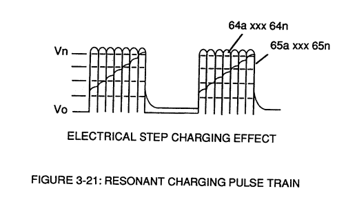
Repetitive formation of electrical voltage force or voltage intensity (65a xxx 65n) of Figure (3-21) attracts and causes liberated electrons (117a,xxx 117n) to move electrically away from gas resonant cavity (410) and physically interact with light bulb filament (115) to initiate and perform kinetic conversion process (390), as further illustrated in (270) of Figure (3-34).
| voltage intensity (65a xxx 65n) of Figure (3-21)
|
kinetic conversion process (390) as to (270) of Figure (3-34)
|
The newly established and on-going electron conversion process (390) continues to aid ionized gas process (260) as other gas atoms (101a xxx 101n) are destabilized into ionized gas vapor (104a xxx 104n).
The electron conversion process (390) is, of course, terminated when applied pulse voltage potential (65) is switched off.
Pulsating voltage potential or voltage intensity (65a xx 65n) is adjusted, also, to "tune-in" to the resonant properties of ambient air gases (101) since ambient air gases (101) exhibits a dielectric value (air-gap of one inch resisting electron arc-over of up to 17,000 volts applied) between voltage plates (E3) and (E4), forming capacitor (410) of Figure (3-34).
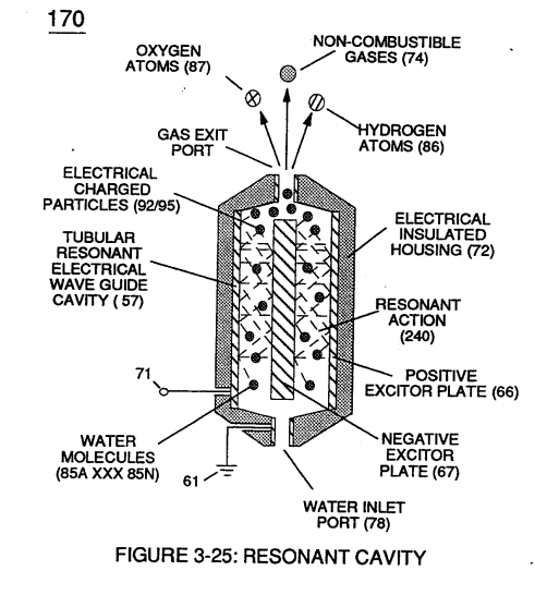
Voltage fields (106/107) are physically configured (skin effect) by T304 stainless steel material to form voltage plates (E3/E4) of Figure (3-33) which are not only chemically inert to gas ionization process (260) but, also, forms tubular Gas Resonant Cavity (410) of Figure (3-34) having approximately the same size and shape of liquid resonant cavity (170) of Figure (3-25), as illustrated in (270) of Figure (3-34).
|
liquid resonant cavity (170) of Figure (3-25)
|
(270) of Figure (3-34).
|
To further destabilize gas atom (104), emitted laser energy (electromagnetic energy having zero mass) (116) is, now, injected into Gas Resonant Cavity (410) via optical lens (121) and superimposed onto gas ionized process (260) and subsequently absorbed by gas atom nucleus (108), as illustrated in (260) of Figure (3-33) as to (270) of Figure (3-34).
|
Figure (3-33)
|
(270) of Figure (3-34)
|
The absorbed laser energy (122) of Figure (3-35) not only causes ionized gas atom orbital electrons (124) to be deflected away from gas atom nucleus (108) but, also, weakens electrostatic force (AA') between gas atom nucleus (108) and deflecting electrons (123a xxx)
... allowing even a greater number of electrons (117a xxx) to be ejected from ionized gas atom (104) being simultaneously subjected to Electron Extraction Process (260), as illustrated in (280) of Figure (3-35).
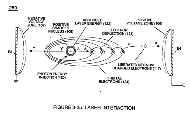
In essence, then, laser interaction (280) along with applied voltage process (260) causes gas atom (101) to go into sub-critical state (destabilizing the mass entity of a gas atom) since absorbed laser energy (122) prevents electrons re-capture (atoms accepting electrons) while interfacing circuit (270) dislodges, captures, and immediately consumes ejected electrons (117a xxx) In other words, ambient air gases (101) has, now, become electromagnetically primed destabilized gas atoms (l04a xxx 100n) having missing electrons.
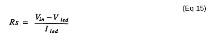
Solid state light-emitting diode (118) of Figure (3-33) arranged in a cluster-array (118a xxx 118n) mounted on printed circuit board (119) emits a discrete wave-length of light energy (electromagnetic energy) when light circuit assembly (420) of Figure (3-43) is electrically pulsed (126a xxx 126n) via variable pulsing circuit (125) in such a way as to vary light intensity (116) to match the light absorption rate of ionized gas (104), and, is determined with respect to the forward current through Led's (118) by (Eq 15)
Where
I led, is the specified forward current (typically 20ma per diode); V led is the led voltage drop (typically 1.7 volts for red emitter's).
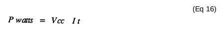
Ohm's law for led circuit in parallel array, and, is given by (Eq 16)
Where
It is the forward current through led cluster-array; Vcc is volts applied (typically 5 volts)
Whereby
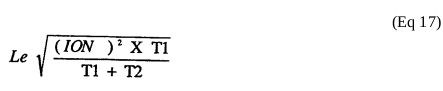
Laser or light intensity is variable as to duty cycle on/off pulse frequency from 1hz up to and
beyond 10khz, and is given by (Eq 17)
Le is light intensity in watts; Tl is current on-time; 1'2 is current off-time; and (ION) = RMS value of
load current during on-period.

In terms of assembly, gas resonant cavity (410), electron extraction circuit (270), optical lens (121) forms gas processor (260) of Figure (3-31).
In retrospect to operational parameters, led's (118) light spectrum (extending from the visible into the Ultraviolet light region) can be selected for a given or predetermined electromagnetically gas priming application (280) since gas nucleus (108) is more responsive to coherent rather than diffused light source.
Applied voltage amplitude (Va xxx Vn), applied voltage pulse frequency (65a xxx 65n), and applied current pulse train (126a xxx 126n) are design variable to "tune-in" to the resonant properties of gas atom (101) while stimulating and performing gas process (260) which attenuates electrical force (AA') of Figure (3-35) to disrupt the mass equilibrium of gas atom (104).
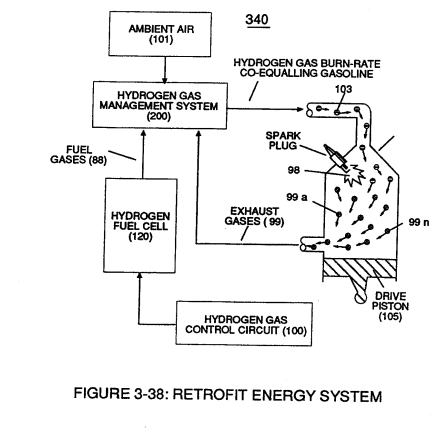
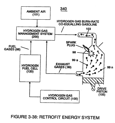
The resultant and newly formed sub-critical gas atoms (104a xxx 104n) are directed onward through air intake manifold (109) of Figure (3-31) to and beyond both exhaust gas metering port (370) and injector port (36) where metered fuel-gas (88), metered exhaust gases (99), and metered sub-critical gas atoms (104a xxx 104n) forms gas-mixture (103) entering engine cylinder (102), as illustrated in (240) of Figure (3-31) as to (340) of Figure (3-38).
|
(240) of Figure (3-31)
|
(340) of Figure (3-38)
|
