Voltage Intensifier Circuit (60)
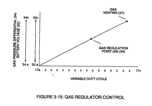
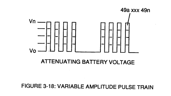
By integrating and joining together variable voltage amplitude control signal (318 xxx 32n) of Figure (3-15) with variable controlled switch-gate (49a xxx 49n) of Figure (3-18) across primary coil (26) of Figure (3-22),
|
Figure (3-15)
|
Figure (3-18)
|
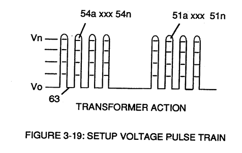
variable amplitude pulse-train (51a xxx 51n) of Figure (3-19) is electromagnetically coupled (transformer action) to secondary coil (52) of Figure (3-22) by way of pulsing core (53) of Figure (3-23) as to Figure (3-22).
|
Figure (3-19)
|
Figure (3-22)
|
Analog voltage signal (32a xxx 32n) of Figure (3-15) allows pulse train (51a xxx 51n) voltage amplitude (V0 xxx Vn) of Figure (3-19) to vary from one up to twelve volts (battery supply 28 of Figure 3-6 by attenuating Laser Accelerator circuit (10) of Figure (3-5) via Hydrogen Gas Control Circuit (100).
|
Figure (3-15)
|
Figure (3-5) |
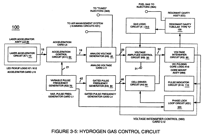
Variable pulse frequency generator (70) of Figure (3-5) varies and adjusts pulse frequency (63) (50% duty cycle pulse) while gated pulse frequency generator (80) of Figure (3-5) varies and adjusts pulse width (54a xxx 54n).
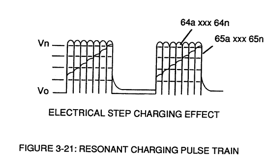
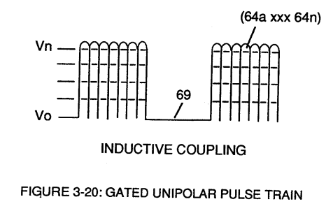
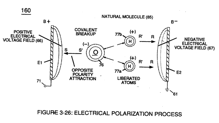
These controlled and variable pulse features are, now, translated to Resonant Charging pulse train (65a xxx 65n) of Figure (3-21) via Unipolar pulse train (64a xxx 64n) of Figure (3-20) during Resonant Action (160) of Figure (3-26) when signal coupling is applied across Resonant Cavity (170) of Figure (3-24) via positive voltage zone (66).
|
Figure (3-21) |
Figure (3-20)
|
|
Figure (3-26) |
Figure (3-24) |
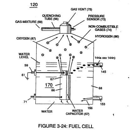
Negative electrical voltage potential (61) of pulse wave (65a xxx 65n) of Figure (3-21) is simultaneously applied to negative voltage zone (67) via Resonant Charging Choke (62) of Figure (3-22) which is electrically linked to opposite end of Primary Coil (26).
The resultant signal coupling ( 65a xx 65n ) of Figure (3-21) is accomplished since primary coil (26), pulsing core (53), secondary coil (52), switching diode (55), resonant charging choke (56), resonant cavity assembly (170), natural water (68), and variable resonant charging choke (62) forms Voltage Intensifier Circuit (60) of Figure (3-22), as illustrated in Figure (3-22) as to Figure (3-23).
|
Figure (3-22)
|
Figure (3-23)
|
Negative electrical ground (61) of voltage Intensifier circuit (60) of Figure (3-22) is electrically isolated from primary electrical ground (48) of Figure (3-22).
Pulsing transformer (26/52) of Figure (3-22) steps up voltage amplitude or voltage potential (Vo xxx Vn) of Figure (3-19) during pulsing operations.
Primary coil (26) is electrically isolated (no electrical connection between primary 26 and secondary coil) to form Voltage Intensifier Circuit (60) of Figure (3-22).
Voltage amplitude or voltage potential (Vo xxx Vn) is increased when secondary coil (52) is wrapped with more turns of wire.
Isolated electrical ground (61) prevents electron flow from input circuit ground (48).
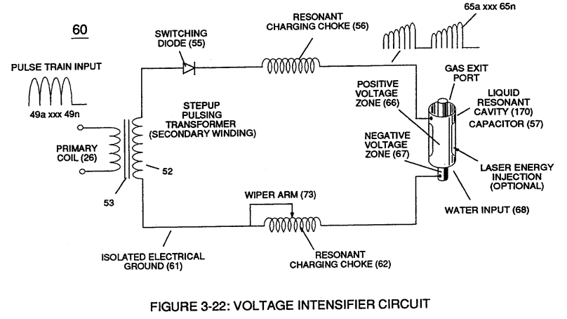 Switching diode (55) of Figure (3-22) not only acts as a blocking diode by preventing electrical "shorting" to secondary coil (52) during pulse off-time (69) of Figure (3-20) since diode (55) "only" conducts electrical energy in the direction of schematic arrow;
but, also, and at the same time functions as an electronic switch which opens electrical circuit (60) during pulse off-time
...allowing magnetic fields of both inductor coils (56/57) to collapse ... forming pulse train (64a xxx 64n).
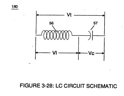
Resonant charging choke (56) in series with Excitor-Array (160) of Figure (25) forms an inductor-capacitor circuit (180) of Figure (3-28) since Excitor-Array (66/67) acts and performs as a capacitor (dielectric liquid between opposite electrical plates) during pulsing operations.
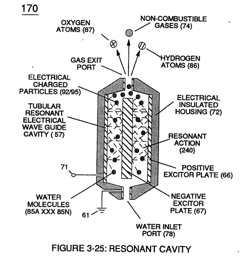 The dielectric properties (insulator to the flow of amps) of natural water (68) of Figure (3-28) as to Figure (3-26)
(dielectric constant of water being 78.54 @ 20C in 1-atm pressure) between electrical plates (66/67)
forms capacitor (57), as illustrated in (170) of Figure (3-25).
|
Figure (3-26)
|
Figure (3-28)
|
Water now becomes part of Voltage Intensifier circuit in the form of "resistance" between electrical ground (67) and pulse-frequency positive potential (66) ... helping to prevent electron flow within pulsing circuit (60) of Figure (3-22).
Inductor (56) and capacitor (57) properties of LC circuit (180) is therefore "tuned" to resonate at a given frequency.
Resonant frequency (63) of Figure (3-19) can be raised or lowered by changing the inductance (56) and/or capacitance (57) valves.
The established resonant frequency is, of course, independent of voltage amplitude, as illustrated in Figure (3-21) as to Figure (3-18).
|
Figure (3-21)
|
Figure (3-18)
|
The value of inductor (56), value of capacitor (57), and the pulse-frequency (63) of voltage (Yo xxx Vn) being applied across the LC circuit determined the impedance of LC circuit (Figure 3-28).
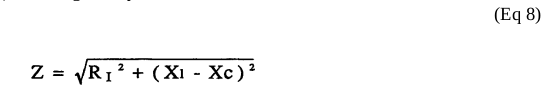
The impedance of inductor (56) and capacitor (57) in series, Z series is given by (Eq 1)
where Resonant frequency (63) of LC circuit in series is given by (Eq 4)
Ohm's law of LC circuit (180) of Figure (3-28) in series is given by (Eq 5)
The voltage across inductor (56) or capacitor (57) is greater than applied voltage (49) of Figure (3-18).
|
Figure (3-18)
|
At frequency close to resonance, the voltage across the individual components is higher than applied voltage (49), and, at resonant frequency, the voltage (Vt) of Figure (3-28) across both inductor and the capacitor are theoretically infinite.
However, physical constraints of components and circuit interaction prevents the voltage from reaching infinity.
The voltage (VI) across inductor (56) is given by equation (Eq 6)
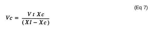
Voltage (Vc) of Figure (3-28) across the capacitor is given by (Eq 7)
During resonant interaction, the incoming unipolar pulse train (64a xxx 64n) of Figure (320) as to Figure (3-21) produces a step charging voltage effect across excitor-array (66/67) (57) as so illustrated in Figure (3-21).
|
Figure (3-21)
|
Voltage intensity increases from zero "ground-state" to a high positive voltage potential in an progressive function.
Once voltage-pulse (64) is terminated or switch-off, voltage potential returns to "ground-state" (61) or near ground-state (diode 55 maintains voltage charged across capacitor 57) to start the voltage deflection process over again as pulse train (64a xxx 64n) continues to be duplicated.
"Voltage intensity or level across excitor array (57) can exceed 20,000 volts due to circuit (60) interaction and is directly related to pulse train (64a xxx 64n) variable amplitude input.
Inductor (56) is made of or composed of resistive wire to further restrict D.C. current flow beyond inductance reaction (Xl), and, is given by (Eq 8)
Variable inductor-coil (62) of Figure (3-22), similar to inductor (56) connected to opposite polarity voltage zone (67) further inhibits electron movement or deflection within voltage intensifier circuit (60).
Movable wiper arm (73) of Figure (3-22) fine "tunes" "resonant action" during pulsing operations.
Inductor (62) in relationship to inductor (56) electrically balances the opposite electrical potential across voltage zone (66/67).
Since pickup coil (52) is also composed of or made of resistive wire-coil, then, total circuit resistance is given by (Eq 9)
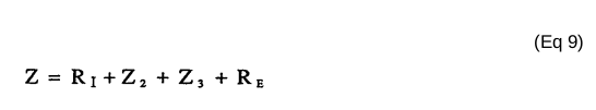
where, RE is the dielectric constant of natural water.
Ohm's law as to applied electrical power, which is (Eq 10)
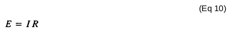
where, (Eq 11)
Whereby,
electrical power (P) is an linear relationship between two variables, voltage (E) and amps (I).
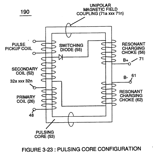 Amp restriction beyond "resonant action" occurs when unipolar magnetic field coupling (71) of Figure (3-23) is allowed to simultaneously drop (pulsating magnetic field) across both resonant charging chokes (56/62) during pulsing operations since electron mass is an electromagnetic entity which is subject to inductor fields (56/62) produced by pulsating magnetic field (71a xxx 71n) of Figure (3-23).
Amp leakage (electron coupling to water) to water bath (68) of Figure (3-24) is further prevented by encapsulating resonant cavity (57) in delrin material (72) of Figure (3-25) which is an electrical insulator to high voltage.
|
Figure (3-24)
|
Figure (3-25)
|

Delrin material (72) insulator value remains intact since insulation material (72) is resilient to water absorption.
Inherently, then, pulsing core (53) of Figure (3-23) aids amp restriction while voltage intensifier circuit (190) is being "tuned" (adjusting pulse train 49a xxx 49n pulse-frequency 63 via pulse frequency generator 70 of figure 3-5) to match the resonant frequency properties of water bath (68) of Figure (3-22), as illustrated in Fuel Cell (120) of Figure (3-24).
|
Figure (3-22)
|
Figure (3-23)
|
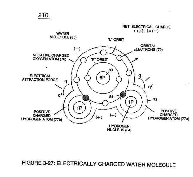
The resultant interfacing voltage circuit (190), now, exposes water molecule (210) of Figure (3-27) to a pulsating high intensity voltage field (65a xxx 65n) of opposite polarity (66/67) while restricting amp flow within circuit (60) of Figure (3-22).
|
Figure (3-22) |
Figure (3-27)
|