Taper Resonant Capacitor (ERt)
Capacitor (ER) is automatically formed when dielectric liquid of water (Re) is placed between Electrical Conducting Plates (E1/E2) of Figure (1-1) page (1-13) (Memo WFC 420).
|
(E1/E2) of Figure (1-1) page (1-13) |
Stainless steel T304 material is used to form Electrical Voltage-Plates (EIIE2) which do "not" chemically interact (chemically inert) (Lab tested less than .0001/year decomposition rate) with liberated water gases (hydrogen _86, oxygen _87, and non-combustible gases W being exposed to an high intensity voltage pulse-field (64a xxx 64n) with negligible amp flow.
Electrical Plates herein called "Excitor" Plates or Voltage Zones (E1/E2) can take-on different configuration of shapes to maximize Dynamic Voltage Potential (600) of Figure (6-3) for different application of usage:
(35a) Traveling Constant Electrical Voltage Wave by way of linear cylindrical resonant cavity (Tubular Cavity 730A),
(35b) Traveling Compressional (concentrating electrical intensity) Electrical Voltage Wave by way of taper cylindrical resonant cavity (730B),
(35c) Traveling Expanding Electrical Voltage wave by way of non-linear cylindrical resonant cavity (730C)
... or any voltage surface combination thereof
... each resonant cavity design acting and functioning as a Voltage Wave-guide (570) and gap-size (35) sufficient enough to allow the "Quenching Effect" to take place, as illustrated in (730) of Figure (7-12) as to (370) of Figure (3-40).
|
(730) of Figure (7-12)
|
(370) of Figure (3-40)
|
The dielectric property of water (being 78.54 ohms @ 25° C) permits the storage of '"Electrical Charge" when a potential voltage difference exists between Electrical Voltage-Plates (E1/E2) as to (E9/E10).
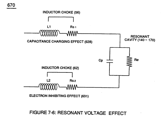
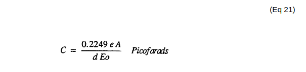
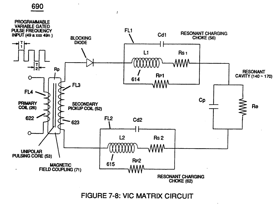
Capacitance (Cp) of Figure (7-6) as to (690) of Figure (7-8) is determined by the surface area (A) of Electrical Voltage-Plates (E1/E2 - E9/E10), the distance (d) between the Electrical Plates (in inches), and the permittivity (Eo) of the dielectric property of water (85) and, is expressed in the following equation:
 |
(690) of Figure (7-8)
|
Where,
(Eo) is Free-Space Permittivity of Water established by VIC Circuit (690) of Figure (7-8) ability to restrict amp flow,
(e/Eo) Ratio is the Dielectric Constant of Water,
(A) is the surface Area of Resonant Cavity and, is expressed in the below equation:
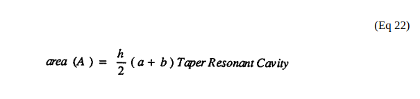
Where,
(h) is longitudinal length of tapered resonant cavity,
(a) being exit pan circumference surface point (E9d) of Figure (6-2),
(b) being cylindrical circumference surface point (E9a) of Figure (6-2) where tapered surface starts,
(a) (b) circumference surface points (E9a)(E9d) respectively determined by below expressed equation:
(see diagram 720 of Figure 7-11)
Where,
(D) is diameter cross section of cylindrical surface at designated point (E9a - E9n),
(x) being mathematical constant 3.1416.
|
diagram 720 of Figure 7-11
|