
Water Fuel Injection System
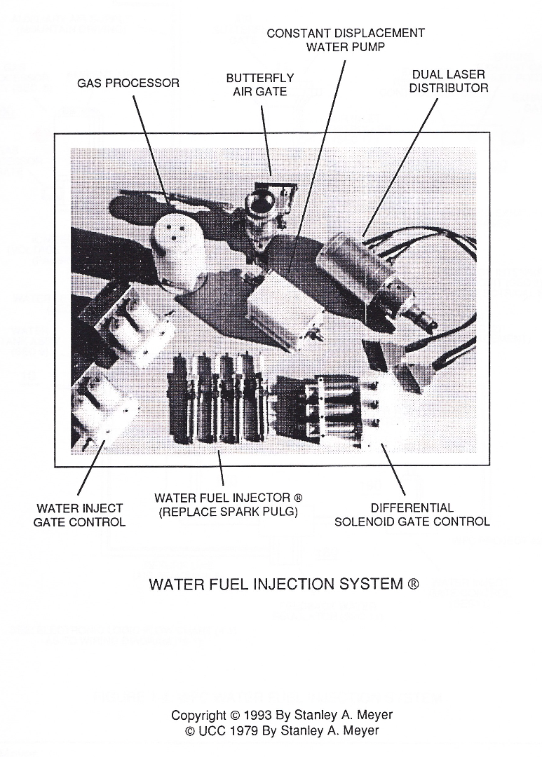
Water Fuel Injection System
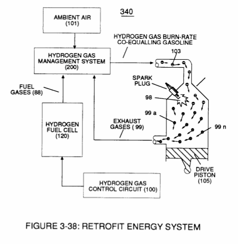
WFC Hydrogen Gas Management System is ideally suited as a retrofit energy system to both reciprocating (rotary piston engine) and turbine jet engines associated with the aviation industry...but in different ways: Reciprocating WFC fuel-kits can be similar to car design (340) of Figure (38) of WFC (422 DA);
Whereas, Water Fuel Injector Kit (10) of Figure (1) can alternately be used as a self-contained Fuel-unit having no pressurized vessel which converts water directly into thermal explosive energy (gtnt) on demand, as illustrated (10) of Figure (1) as to Figure (40) of Figure (2B 1-2).
 |
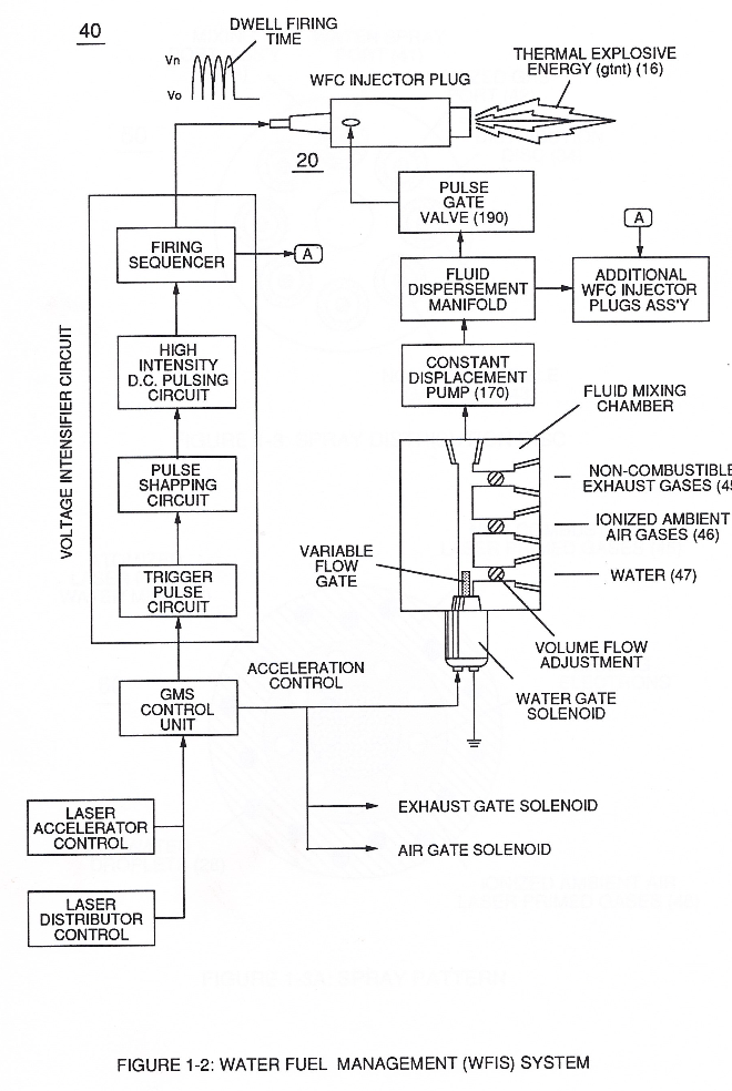 |
Operationally, Water Fuel injector assembly (10) of Figure (1) as to (40) of Figure (2B) performs several functions simultaneously to produce thermal explosive energy-yield (gtnt) (16) on demand:
First water mist (47) of Figure (1-3A) is injected into fuel-mixing chamber (35) of Figure (3B) by way of water spray ports (41a xxx 41n) of Figure (3A);
Secondly, ionized air gases (46a xxx 46n) of Figure (3A) (laser primed ambient air gases having missing electrons) produced by Ambient Air Ionizer (80) of Figure (4) as to Figure (1) and non-combustible gases (45) of Figure (3A) are intermixed with expelling water mist (47a xxx 47n) to form Water-fuel mixture (48) by way of gas mixing disc (34) of Figure (3B) as to (30) of Figure (2A);
thirdly, the resultant moving Water-Fuel mixture (48) of Figure (3B) enters into Voltage Igniter Stage (180) of Figure (3B) and exposed to high intensity voltage fields (33 / 36) (typically 2,000 volts or above @ 10 Khz or above) opposite electrical polarity (E7 / E8)
...which, in turn, not only performs electrical polarization process (160) of Figure (25) undergoing Dielectric Resonant (240) of Figure (30); but, also sets up and triggers Hydrogen Fracturing Process (390) of Figure (41) as to Figure (6) under control state (on demand) via electrical-static spark ignition (49 / 51) of Figure (3B)....releasing thermal explosive energy (gtnt) (16) passing beyond gas exit port (32) of Figure (3B), as further illustrated in Figure (2) as to Figure (1).
To ensure proper energy-flame projection and subsequent energy-flame stability, constant placement water pump (170) causes and allows ionized ambient air gases (46), non-combustible gases (45), and water (47) to be displaced under static pressure up to and beyond 125 psi respectively.
Energy-Flame density is enhanced and sustained by causing ionized gases (46a xxx 46n) of spray port (42) to be deflected into liquid spray path (41), together water mist (47) and ionized air (46) are, now, directed toward and deflected through non-combustible gas spray path producing uniformed water-fuel mixture (48), as illustrated in Figure (3B).
Energy-Flame temperature is regulated by controlling the volume flow-rate of each fluid mediums (47 / 45/ 46) in direct relationship to applied voltage intensity (33 /36), as further stated in Figure (2B) as to Figure (3B).
To elevate Energy-flame-temperature still further, help increase fluid-displacement (46/47) while maintaining or reducing the volume flow rate of non-combustible gases (45) during an increase of applied voltage amplitude (Vo x Vn) of Figure
(32) as to Voltage Intensifier Circuit (110) of Figure (7) and Electron Extraction Circuit (120) of Figure (8).
To lower Energy-flame temperature simply increase the amount of non-combustible gas (45a xxx) or reduced the fluid flow rate (45 / 46/ 47)) uniformly while lowering pulse voltage amplitude (xxx Vo).
To establish a predetermined or given Energy-flame temperature adjust fluid-medium (45 / 46 / 47)) and applied voltage amplitude (Vo xxx) independent of each other to obtain the desired results.
The resultant energy-flame pattern is further maintained by allowing the ignited,compressed, and moving gases (29) of Figure (3B) to be projected to, pass through and beyond nozzle-port (32) under pressure due to gas expansion caused by thermal gas ignition.
Voltage Igniter Stage (180) of Figure (3B) as to Voltage Intensifier Circuit (110) Figure (7) as to Extraction Circuit (120) of Figure (8) performs several functions simultaneously to initiate and trigger thermal explosive energy-yield (gtnt) (16) beyond normal gas burning levels:
Water droplets (28a xxx 28n) escaping from spray-mist (47) and exposed to high intensity voltage fields of opposite polarity 33/ 36) are stimulated to undergo Electrical Polarization Process (160) of Figure (25)...which not only separates and splits the unlike atoms of the water molecule but also causes the unlike atoms (hydrogen atoms 77a / 77b and oxygen atom 76) to experience electron ejection (230) of Figure (29) as to (71) of Figure (8) since voltage intensifier circuit (110) of Figure (7) inhibits and prevents electron flow to enter into gas ignition process (180), as further illustrated in Figure (6).
The newly liberated water molecule atoms (oxygen 76 and hydrogen atoms 77a / 77b) immediately interact with laser primed ionized ambient air gases (7a xxx In of Figure 1-8) (see WFC memo 420) to cause the resultant highly energized and mass destabilized combustible gas atoms (93a xxx 93n) of Figure (8) to perform Hydrogen Fracturing Process (80) of Figure (7)
when electrostatic force (14/16) thermally ignites (kinetic agitation) destabilized water-fuel mixture (93a xxx 93n) under gas compression... preventing the formation of the water molecule during thermal gas ignition....satisfying Energy Gas Detonation Equation.
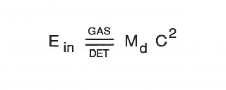
which states:
That, whenever the mass-size of a combustible gas atom is decreased (Md), thermal explosive energy-yield (gtnt) is increased (Ein) during thermal gas combustion (Gas // Detonation.), as so illustrated in (100) Figure (6) as to (90) of Figure (5).
Incoming ambient air gases (5a xxx 5n) become laser primed and ionized when passing through Ambient Air Ionizer (Gas Processor) (80) of Figure (4) as to (10) of Figure (1) since electron extraction circuit (120) of Figure (8) not only captures and consumes ejected electrons (7a cx 7n) of Figure (6); but, also prevents electron flow into destabilizing gas process (180), as so illustrated in Figure (3B).
In terms of performance reliability and safety, ionized air gases (46a xxx 46n) and liquid water (47a xxx 47n) do not become energy activated (volatile) until water-fuel mixture (48) reaches Voltage Igniter Stage (180).
Injected non-combustible gases (45a xxx 45) retards and controls the combustion rate of the Hydrogen Fracturing Process (100) of Figure (6) during gas-ignition.
In other or alternate applications, laser primed ionized liquid oxygen (68) of Figure (1-10) CF* memo 420) and laser primed liquid hydrogen (69) of Figure (1-10) stored in separate fuel tanks can be used in place of fuel-mixture (48); or, liquefied ambient air gases (6) alone with source (8) can, also, be substituted as a fuel-source (48) to trigger Hydrogen Fracturing 10).
Additional WFC Injector Assemblies (20) of Figure (2) are arranged in cluster array (20a xxx 20n) to increase energy-yield output (16a xxx 16n) of Figure (10 / 1 / 12).
WFC injector assembly (10) of Figure (1) as to (30) of Figure (2A) is design variable to be retrofitable by replacing fossil-fuel injector ports affixed to jet engines (see Figure 11), heating systems (Figure 10), rockets engines (Figure 12), or even car spark plugs (130) of Figure (9) which simply uses Water Fuel management (WFMS) system fluid-metering system (40) to control
gas ignition (16), as illustrated in (40) of Figure (2B).
Sequential pulsing of Water Fuel Injector (20/30) of Figure (1) as to (40) of Figure (2B) is system activated by Pulse Gate Valve (190) of Figure (1) to further control a predetermined energy-flame (16).
In essence, then, the Water Fuel Injector system (40) simply processes and converts water into a useful hydrogen fuel on demand at the point of gas ignition...thereby, co-equally or superseding fossil-fuel safety standards...
especially when ionized ambient air gases (46a xxx 46n) and non-combustible gases (45a xxx 45n) are intermixed with water supply (47) prior to entering.
Water Fuel Injector Plug (20 / 30), as illustrated in (40) of Figure (2B) as to (10) of Figure (1).