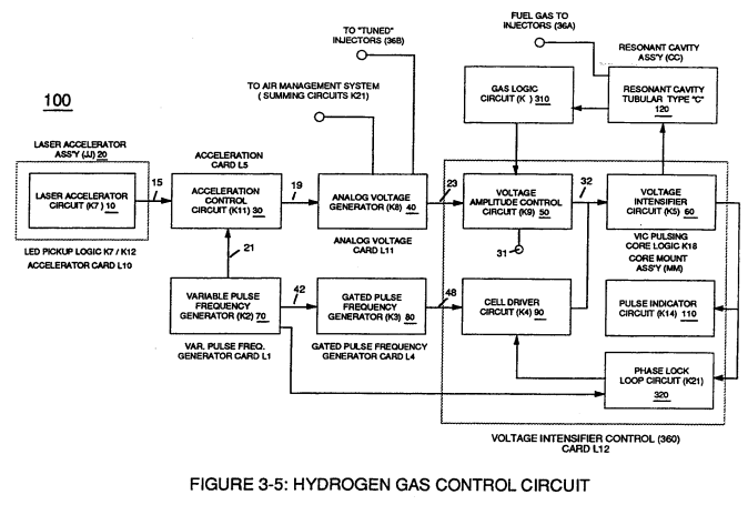
Variable Pulse Frequency Generator (70)
Circuit (70) of Figure (3-5) is a multi pulse-frequency generator which produces several clock pulses (simultaneously) having different pulse-frequency but maintaining a 50% duty cycle pulse (39) configuration, as illustrated in Figure (3-16).
|
Figure (3-5)
|
Figure (3-16)
|
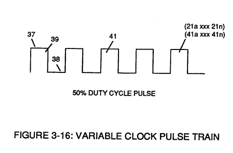
Pulse on-time (37) and pulse off-time (38) are equally displaced to form duty pulse (39) which is duplicated in succession to produce pulse train (41) of Figure (3-16).
Increasing the number of duty pulses (39a xxx 39n) up to pulse frequency range of 10Khz or above now forms clock signal (21) of Figure (3-5) which, in turns, performs the scanning function of Acceleration Control Circuit (30) of Figure (3-5).
Circuit (70) also produces another independent and separate clock signal (41a xxx 41n) which is electrically transmitted to and become incoming clock signal (42) for Gated Pulse Frequency Generator Circuit (80) of Figure (3-5).
In both cases, pulse frequency range of each clock signal (21) and (42) can be altered or change (controlled independent of each other) to obtain peak performance of Fuel Cell System (100) of Figure (3-5).