
Funneling Effect
 Enhancement of the operational parameters of Hydrogen Fracturing Process (100) of Figure (6) is further exemplified when incoming Resonant voltage-wave (58) of Figure (18) electrically transmitted across Resonant Cavity Zone (35) during water injection cycle...
causing Resonant Cavity Zone (35) to function and perform as a voltage wave-guide (86) of Figure (14) since the gradual decrease in cross-sectional circumference area (85) of Figure (14) is in linear progression ... reducing both voltage surfaces areas (83/84) in parallel space relationship from larger segmental area (85a) to smaller segmental area (85n).
 This resultant "Funneling Effect" (260), now, allows voltage amplitude (Vn) wave-form (58) to travel the length of Resonant Cavity Zone (35) from Start-Point (85a) to End-Point (85n) increasing voltage intensity (xxx VL = Vn) as parallel voltage surfaces (83/84) diminishes in size relationship (85a ~ 85n), as illustrated in (210) of Figure (17).
This "progressive" increase in voltage intensity (VL ~= Vn) due to the "Funneling Effect", now, allows several gas processing functions to occur in a instant of time:
Voltage amplitude level VL of Pulse-wave (58) is predetermined (20,000 V.D.C. typically) to start and cause Electrical Polarization Process (160) at a relative rapid rate of gas production at segmental point (85a) when voltage point (VL xx Va) is reached.
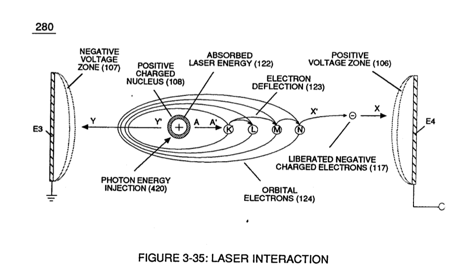
As voltage intensity increases (VL x Va x Vb) onward segmental point (85b), Energy Pumping Action (520) of Figure (4-3) (WFC Memo 424) as to (280) of Figure (34) (WFC Memo 422 DA) is activated to peak performance levels.
|
(520) of Figure (4-3)
|
(280) of Figure (34)
|
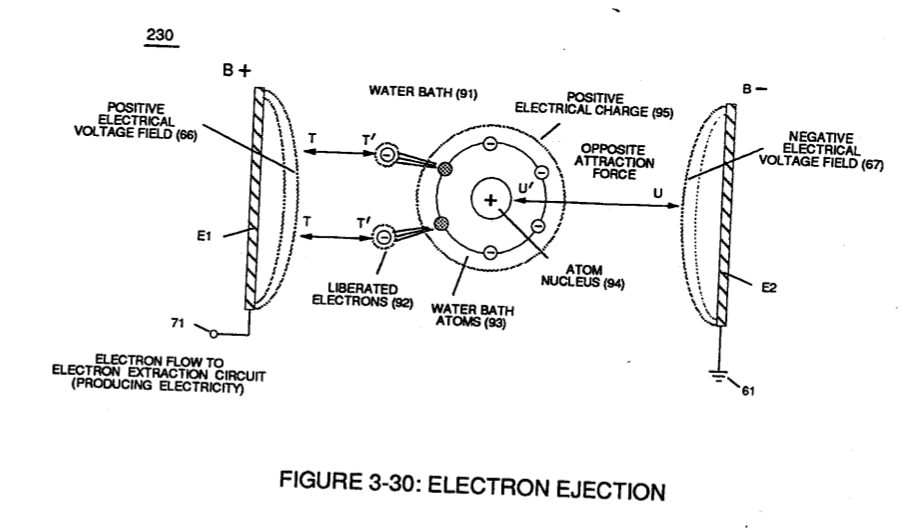
At segmental point (85c) voltage intensity (VL x Va x Vb x Vc) is increased sufficiently enough to propagate Gas Ionization Process (230) of Figure (3-30) (WFC Memo 422 DA).
At termination point (85), voltage intensity (VL x Va x Vb x Vc x Vn) is, now, increased to the point to cause Gas Ignition as Combustible Gas Atoms (76, 77a - 77b) which are, then, expelled from Gas Nozzle Port (87) of Figure (14) under dynamic pressure to allow thermal gas expansion (16) ... releasing thermal explosive energy (gtnt) beyond and away from Resonant Cavity Chamber (180), as illustrated in Figure (14).
To prevent pre-ignition of gases traveling toward Exit-Port (87), Resonant Cavity (35) open space (open resonant cavity) parallel dimension between positive voltage surface (82) and negative voltage surface (83) is small enough (typically .010 or so) to function as a Quenching Circuit, as illustrated in Figure (24SD) (missing image) (WFC Memo 420).
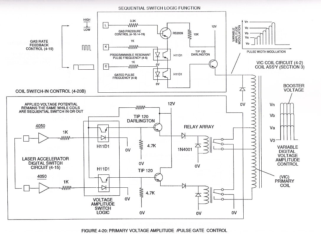
To increase energy levels (16a xxx 16L = 16n) of Hydrogen Fracturing Process (100) as to (390), even further, simply switch-on additional Booster Coils (61a x 61L - 61n) in sequential order to increase voltage intensity (VL ~ Vn ~ Vm) to higher magnitude of "Electrical Force" (Vma xxx Vmn) which is due to the inductance/capacitance values of each succeeding coil-structure (61a x 61n) forming Booster coil-Assembly (250), as illustrated in (240) of Figure (20).
|
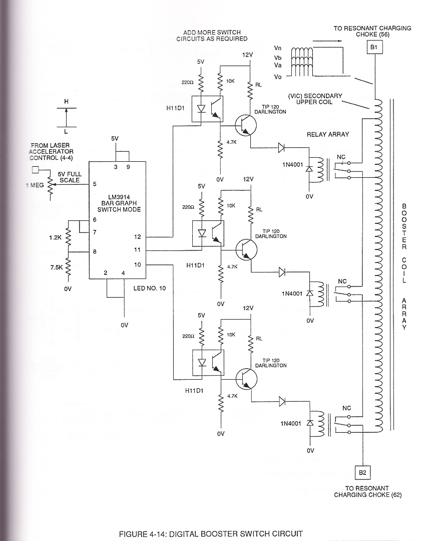 |
To return or lower Voltage Intensity (xxx Vmn) to Secondary Voltage Level (71), once again, inductance core-slug (73) (magnetic core material) advances (via solenoid Control 74) toward, passes through inside coil-wrap (250) in linear manner to "Switch-Off" each adjacent coil-stage (61a xxx 61n) by "Shunting" or "Redirecting" induced voltage intensity (Vmn xxx Vma) to its respective electrical out-put leads (72n - 72c - 72b - 72a), as shown in Figure (20).
This "Shunting Effect" occurs when the magnetic field strength of each individual coil-structure (61) (being electrically energized) induces and forms magnetic core-field (75) which opposes and stops current flow within the exposed coil-stage (61a-61b-61c-61n).
This resultant "Shunting Effect", now, allows voltage intensity (Vma = Vmn) to be placed across Resonant Cavity Zone (35) to not only compensate for water impurity that might alter the operational parameters of Hydrogen Fracturing Process (100) as to (390) but, also, provide "Instant" "Power-Boost" when needed.
|
 |
The established "Power Boost" energy level (16a xxx 16n) is changeable, however, by, simply, electrically moving or displacing (back and forth movement) Core-Slug (73) to another stop-location (72)... adjusting energy-level (16a xxx) on demand.
In alternate form, Core-Slug (73) is replaced by a series of Choke Coils (77a xxx 77n) arranged in such a way as to increase voltage Intensity (Voltage Pulse Amplitude) (VL ~ Vn xxx) digitally by sequentially switching-on / switching -off Choke Coils (77a xxx 77n) to allow applied Voltage Intensity (VL ~ Vn xxx) to be placed across Voltage Expander Coils (78a xxx 78n) in direct relationship to electrically energized shunt-coil (76).
For example, as adjacent Shunt-Coil (76b) is switch-on while, simultaneously, Choke Coil (76a) is switch-off by Electronic Switch Circuit (79), Voltage Intensity (VL ~ Vn xxx) is increased due to inductance / capacitance of Voltage Expander Coil (78a) which is, now, added to Electrical Circuit (250) by electrical pathway (82a) since electromagnetic coupling field (76b) prevents electron flow to cause open circuit (82b)...
(missing content)
thereby establishing Voltage Level Logic Function (260) which is electronically transferable in sequential order (260a xxx 260n) by Laser Acceleration Control Circuit (4-4) of (220) of Figure (18).
thereby, attenuating voltage amplitude (voltage intensity) beyond Secondary Coil (53) voltage levels (71), as illustrated in (220) of Figure (18).
Attenuating variable voltage amplitude (72a xxx 72n) in conjunction with incoming gated pulse-train (210a xxx 210n), now, expands gated pulse width (76a xxx 76n) as voltage amplitudes (Vo xxx Vn) increases, forming step up voltage wave Form (77) of Figure (17).
This newly formed synchronized and repetitive dual expanding voltage wave form (77a xxx 77n) is further enhanced by "Funneling Effect" (260)... maximizing voltage dynamic across Resonant Cavity (35) always subjecting and exerting increase "Electrical-Stress" (SS'-RR' / TT'-UU') of opposite polarity across Hydrogen Fracturing Process (100 / 390) to the point of gas ignition.