
Instant Explosion of Water
The "mode-of-operability" of VIC Coil Assembly allows Voltage Potential of opposite voltage polarity to increase and be attenuated up to and beyond 20 Kilovolts while inhibiting and restricting amp leakage in the milliamperes range ... establishing operational parameter of utilizing "Opposite Electrical Attraction Force" of "high voltage intensity" to "instantly" releases thermal explosive energy (gtnt) from natural water.
The Voltage Intensifier Circuit takes advantage of the "Electron Bounce Phenomenon" to trigger Hydrogen Fracturing Process without amp influxing. Taper Resonant Cavity functions as a "Voltage Amplifier" when interlinked with VIC Circuit.
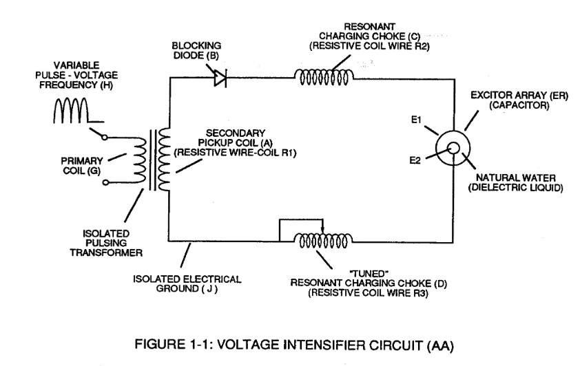
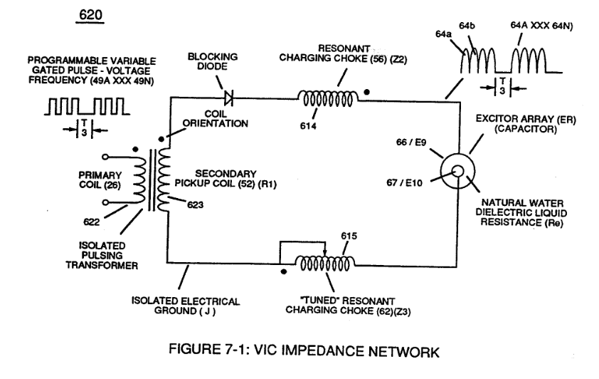
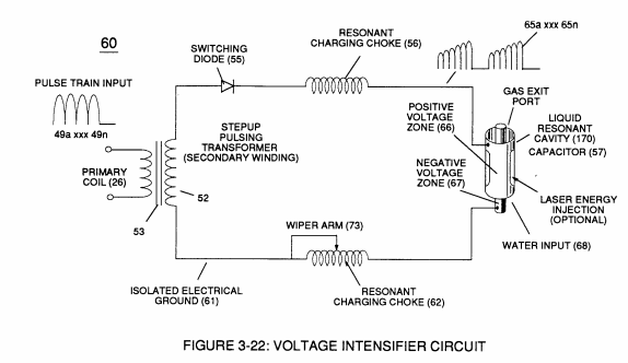
Voltage Intensifier Circuit (60) of Figure (3-22) (Memo WFC 422 DA) as to Figure (1-1) (Memo WFC 420) and Voltage Intensifier Circuit (620) of Figure (7-1) are specifically designed to restrict amp flow during Programmable Pulsing Operations (49a xxx 49n) but in different operational modes:
|
Voltage Intensifier Circuit (60) of Figure (3-22)
|
Figure (1-1) (Memo WFC 420)
|
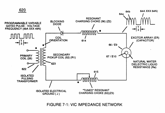
Voltage Intensifier Circuit (620) of Figure (7-1)
|
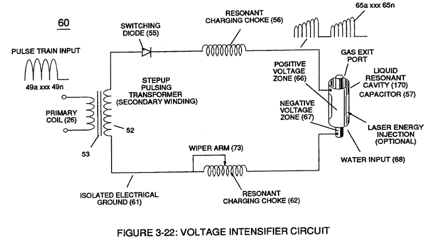
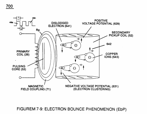
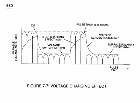
VIC voltage circuit (60) utilizes copper wire-wrap to form Resonant Charging Chokes (56/62) of Figure (3-22) in conjunction with Switching Diode (55) to encourage and make use of "Electron Bounce" phenomena (700) of Figure (7-9) to help promote Step Charging Effect (628) of Figure (7-7) by preventing electrical discharge of Resonant Cavity (140 - 170) since Blocking Diode functions as an "Open" switch during Pulse Off-time;
|
(56/62) of Figure (3-22)
|
(700) of Figure (7-9)
|
|
(628) of Figure (7-7)
|
whereas,
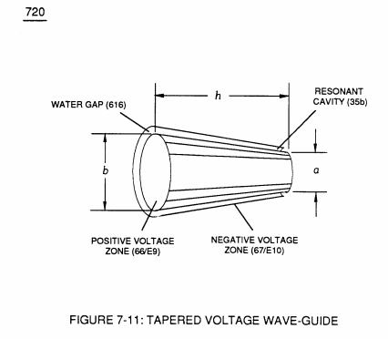
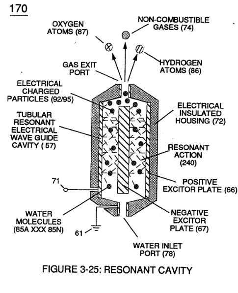
VIC Voltage Enhancement Circuit (VIC - VB) (620) of Figure (7-1) incorporates the use of stainless steel wire-wrap coils (614/615) to accomplish the formation of unipolar gated pulse-wave (64a xxx T3 xxx 64n) without experiencing "signal distortion" or "signal degradation" (preventing transformer ringing during signal propagation) as elevated voltage levels ( - xx Vc- xx Vd - xx Vn) while allowing the reduction of Capacitor-Gap (Cp) (616) of Figure (7-11) width spacing (57 of Figure 3- 25 ~35 of Figure 6-2) (typically .060 - .010) respectively as illustrated in Tubular Resonant Cavity (170) as to Taper Resonant Cavity (620) of Figure (7-1).
|
(VIC - VB) (620) of Figure (7-1)
|
(616) of Figure (7-11)
|
|
(57 of Figure 3- 25 ~35 of Figure 6-2)
|
|
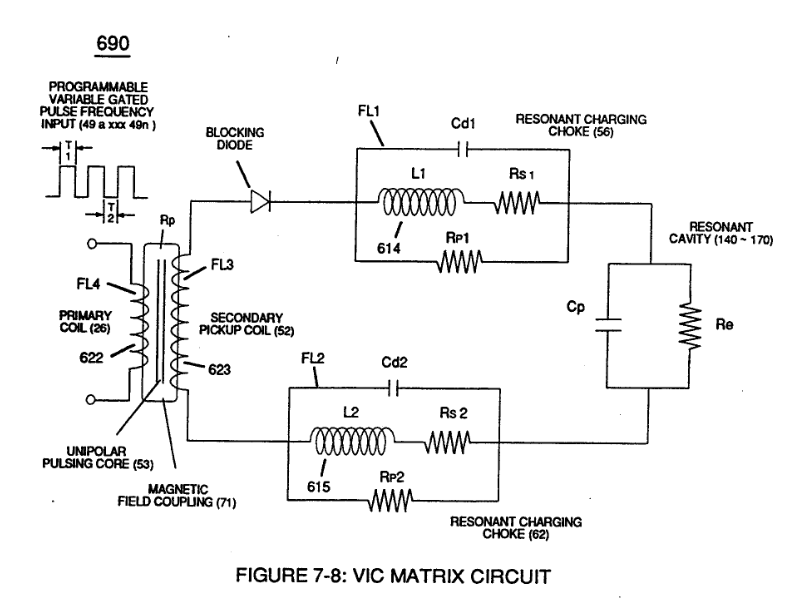
Switching Diode (55) of Figure (3-22) prevents Bidirectional electron flow (current flow in one direction only) since Blocking Diode (55) only conducts "current flow" in the direction of schematic-arrow while being placed in-line with VIC Circuit impedance interaction (R1 + Z2 + Z3 + Re), as mathematically extrapolated in Circuit Equation (Eq 9)
|
(55) of Figure (3-22)
|
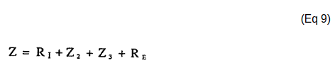 |
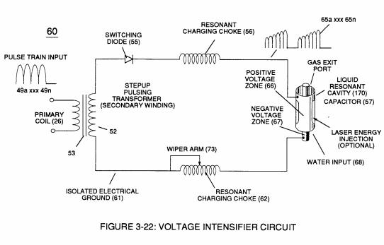
... Diode (55) being placed between Secondary Pickup Coil (52) and Resonant Charging Choke (56) to act as an electronic switch in open-position during pulse off-time (T2) of Figure (7-8) while preventing electron flow in reverse direction when Inductor (L1) collapsing electromagnetic field (FL1) produces another unipolar pulse wave-form (64a - 64b).
|
(T2) of Figure (7-8)
|
... producing unipolar voltage wave-form (64a xxx 64n) during repeated pulse-signal (46a xxx 46n) on-time (T1a xxx T1n)
... allowing the formation of an gated pulse-frequency pulse-train (64a/64b - T3 - 64a/64b) when pulse off-time (T3) is greater than time-period (T2)
... input-signal (49a xxx 49n) being a Pulse-Train where (T2) pulse offtime (T2) is adjusted to allow Unipolar Pulse-Train (64a xxx T3 xxx 64n)
... outputting Voltage-wave signal (64a xxx 64n) being a pulse-frequency doubler due to Inductance Reactance (FL) of Inductor Coil (56) of Figure (3-22) when collapsing magnetic field (FL) of Figure (7-3b) re-cuts coil-wrap (Ll) during each pulse off-time (T2)
|
(56) of Figure (3-22)
|
(FI) of Figure (7-3b)
|
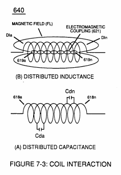
... producing a second unipolar voltage wave-form (64b) during the rise and fall of magnetic field (71), as further illustrated in (620) of Figure (7-1)
|
(620) of Figure (7-1)
|