RLC CIRCUIT
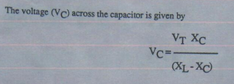
The voltage (VC) across the capacitor is given by:
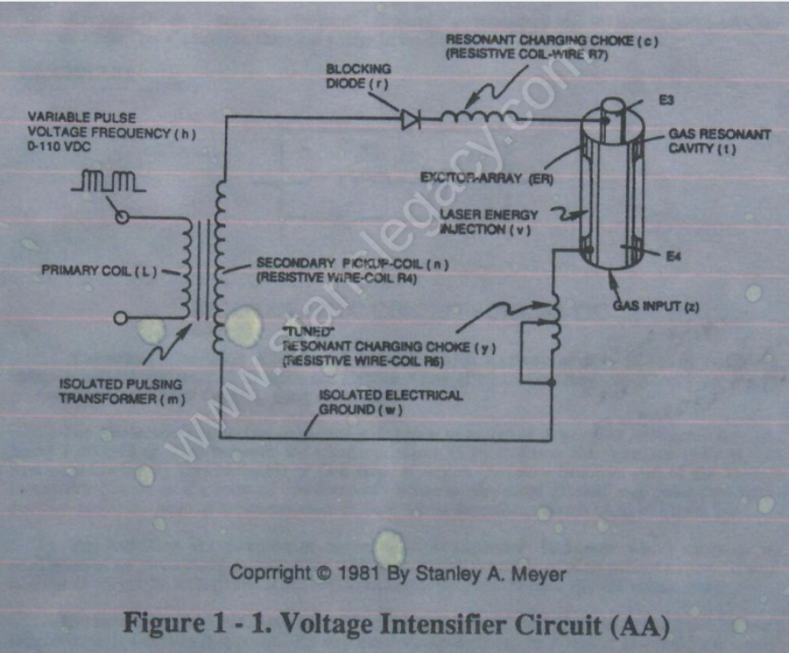
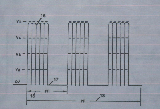
During resonant interaction, the incoming unipolar pulse-train (h) of Figure (1-1) as to Figure (9B) produces an step-charging voltage-effect across Excitor-Array (ER of t), as illustrated in Figure progressive function.
 Figure 1-1 Figure 1-1 |
Figure 9B |
Once the voltage-pulse is terminated or shut-off, voltage potential returns to an "ground-state" or near ground-state to start the voltage deflection process over again.
Voltage intensity or level across Excitor-Array (ER of t) can exceed 20,000 volts due to circuit (AA) interaction and is directly related to pulse-train (h) variable amplitude input.
RLC CIRCUIT
Inductor (c) is made of or composed of resistive wire (R7) to further restrict D.C. current flow beyond inductance reaction (XL), and is given by
Dual-inline RLC NETWORK
Variable inductor-coil (y), similar to inductor (c) connected to opposite polarity voltage zone (E4) further inhibits electron movement or deflection within the Voltage Intensifier Circuit.
Moveable wiper arm fine “tunes” "Resonant Action" during pulsing operations.
Inductor (y) in relationship to inductor (c) electrically balances the opposite voltage electrical potential across voltage zones (E3/E4).
VIC RESISTANCE
Since pickup coil (n) is also composed of or made of resistive wire-coil (R4), then, total circuit resistance is given by
Where, RE is the dielectric constant of Argon (Ar).


