
Laser Accelerator Assembly
Laser Accelerator Circuit (10) of Figure (4) which is a component part of Laser Accelerator Assembly (20) of Figure (3-10) uses a GaAs infrared emitting diode (1) of figure (3-9) to trigger a SDP8611 Optoschmitt light receiver (2) of Figure (3-9) from quiescent state ( output logic high ... B+) (13) to on-state (the minimum irradiance that will switch the output low) which switches or triggers the Optoschmitt (2) output to ground state (zero volts) (12).
|
Laser Accelerator Assembly (20) of Figure (3-10)
|
SDP8611 Optoschmitt light receiver (2) of Figure (3-9) |
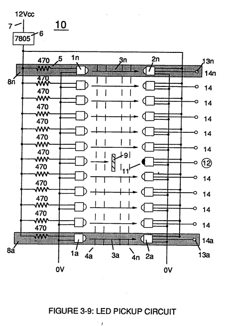
The peak wavelength (3) of Figure (3-9) being transmitted from the infrared emitting diode (led) (1) to the Optoschmitt receiver (2) is typically (935 nm) and allows the Optoschmitt (2) clock frequency (the speed by which the Optoschmitt changes logic state) to be (100 kHz).
Optical lens (4) of Figure (310) redirects and focuses the transmitted light source (3) of Figure (3-9) (traveling infrared light waves) to the Optoschmitt (2) by passing the light source through a series of concentric lenses (4a xxx 4n) of Figure (3-10) which become progressively smaller from the outer peripheral lens surface (4a) to the inner lens surface (4n).
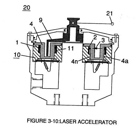 The spatially concentric lenses (4a xxx 4n) of Figure (3-10) causes the beam angle of the light source to trigger the Optoschmitt (2) beyond the minimum irradiance that is needed to switch the Optoschmitt from quiescent state (high logic state I B+ ) to on-state (output changing to zero volts).
The Derate linearly of light intensity is approximately 1.25mWj degree C above 25 degree C at a spatial distance of .500 inches between the two infrared devices (1)(2) of Figure (3-9) as to Figure (3-10).
Transmitted light source (3) is turned-on when a electrical power source of 5 volts is applied to the led (1) through dropping resister (5) by way of voltage regulator (6) connected to the car electrical system (7).
Together, the matched infrared devices (1)(2) with optical lens (4) forms optical circuit (8) of Figure (3-9).
Grouping additional optical circuits (8a xxx 8n) in an inline or linear arrangement, now, forms Led Pickup Circuit (10) of Figure (3-9), as shown in Figure assembly (20) of Figure (3-10).
|
Led Pickup Circuit (10) of Figure (3-9)
|
Figure assembly (20) of Figure (3-10)
|
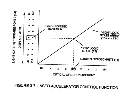 To perform a switch-logic function, light - gate (9) of Figure (3-9) as to Figure (3-10) is inserted between the matched infrared devices (1)(2) and moved in a linear displacement from one optical circuit (8x) to another optical circuit (8xx), as illustrated in Figure (3-9)(3-10) as to Figure (3-7).
Once light-gate (9) blocks and prevents traveling light-beam (3) from reaching the matched Optoschmitt (8xx), the darken Optoschmitt (11) (non-energized) changes output state since the irradiance energy level (3) is reduced to, or below the release point...triggering opposite logic state (12).
As light-gate (9) advances to the next optical circuit (8xxx) a new and separate low-state logic function (12) occurs while the previous optical circuit (8xx) reverts back to high-state logic (13).
Advancing light-gate (9) still further performs the same opposite (alternate) logic-state switching in a sequential manner until the advancing light-gate (9) reaches the last optical circuit (8n).
Reversing the movement of light gate (9) performs the same high to low logic switch-function but in reverse sequential order.
Reversing the direction of the light-gate (9) once again reinstates the original sequential switching order, as illustrated in Figure (3-7) and Figure (3-9).
Longevity and reliability of component life is typically 100,000 hours since led pickup circuit (10) of figure (3-9) utilizes no mechanical contacts to perform the sequential logic switch function.
Light-gate (9) integrated with led pickup circuit (10) make up Laser Accelerator assembly (20), as shown in Figure (3-10).
Light-gate (9) of Figure (3-10) is mechanically linked to the car acceleration pedal by way of cabling hookup (22).
Opposite placement of the matched infrared devices (1)(2) prevents bogus or false triggering of "low" logic state (12) during light-gate displacement (9a xxx 9n) of Figure (6)(7) and (8).
If light emitting diodes (led) (la xxx In) of figure (8) are electrically disconnected from D.C. power supply (6), then Led Pickup Circuit (10) outputs are switch to "low" logic state (l2a xxx 12n) which disallows "low" logic state signal (12), resulting in a "shut-down" condition to Hydrogen Gas Control Circuit (200) of Figure (3-1).
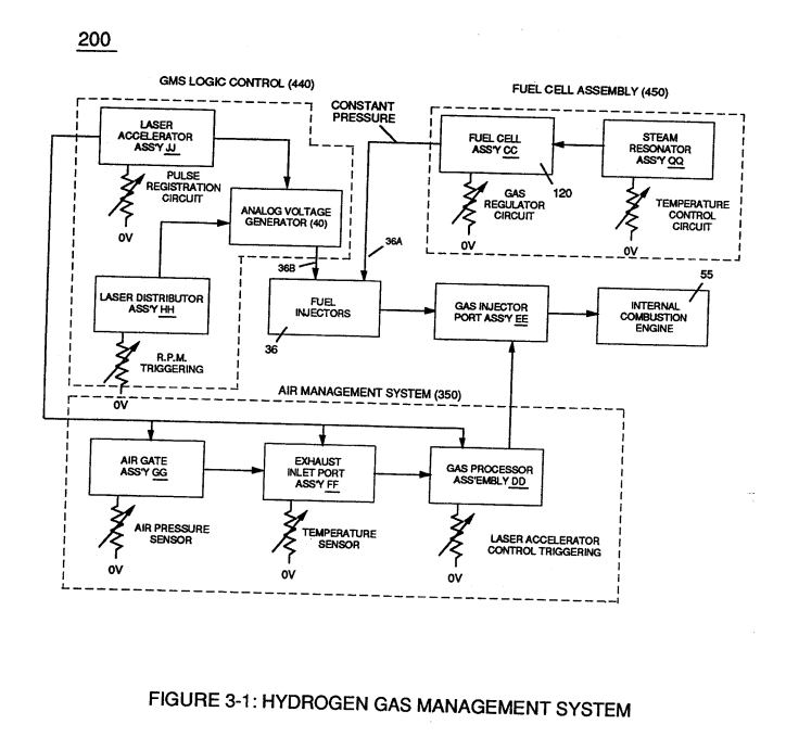
Disconnection of power supply (6) to Optoschmitt array (2a xxx 2n) of Figure (3-9) results in a similar "shut down" condition to control circuit (200), as further shown in Figure (3-1).
This "shut-down" or "Switch-off" condition helps provide a fail-safe operable Fuel Cell (120) of Figure (3-20) by negating acceleration beyond driver's control.