
Laser Distributor
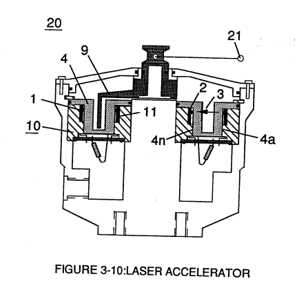
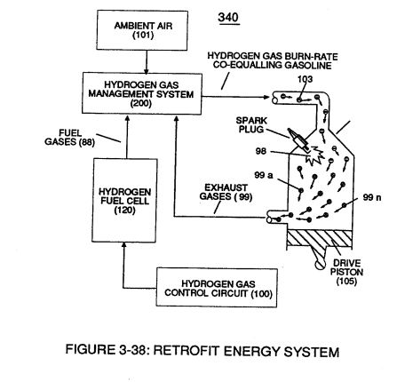
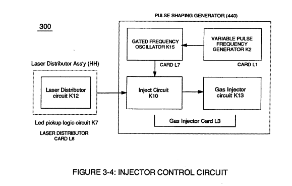
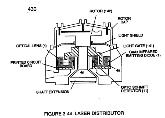 Laser Distributor assembly (430) of Figure (3-44) functions in similar manner as Laser Accelerator (20) of Figure (3-10) except light-gate (141) of Figure (3-44) rotates in the same direction of Spark-rotor (142) and being displaced opposite to rotor blade (142), allowing intermixed processed ambient air gases (101) and Fuel-Gases (88) to enter engine cylinder (102) of Figure (3-38), as illustrated in Injector Control Circuit (300) of Figure (3-4).
|
Laser Accelerator (20) of Figure (3-10)
|
engine cylinder (102) of Figure (3-38) |
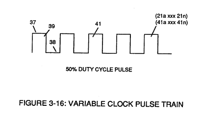
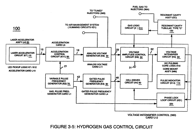
Rotating light-gate triggering circuit assembly (430) sequentially activates Pulse Shaping Generator (440) of Figure (3-4) to produce a constant 50% Duty-cycle Pulse-Train (see Figure 3-16 once again) to Analog voltage Generator (40) of Hydrogen Gas Management System (200) of Figure (3-1) as to Figure (3-5).
|
Figure (3-1)
|
Figure (3-4)
|
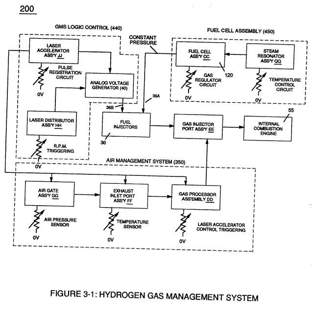
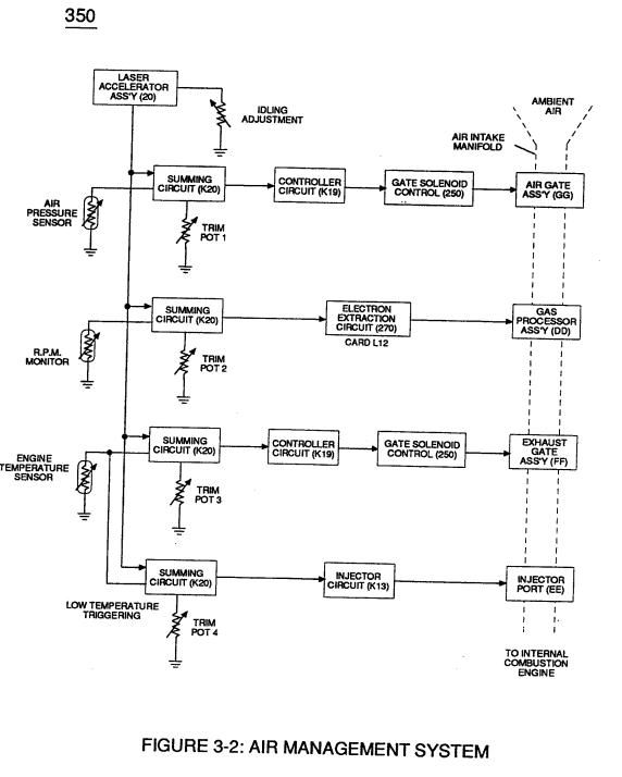
Interlocking Laser Accelerator output {JJ) with Laser Distributor output (HH) of Figure (3-1) causes Fuel-Injectors (36) to be "Tuned" with both Air Management System (350) of Figure (3-2) and Hydrogen Gas Control Circuit (100) of Figure (3-5) to maintain constant Fuel-mixing Ratio (290) of Figure (3-3) during engine performance.
|
Figure (3-2)
|
Figure (3-5)
|
As Laser Accelerator (JJ) advances toward "Peak" engine performance, Fuel-Injectors (36) open gate-time (on-time) increases proportionally.
Opposite or reverse movement of Laser Accelerator (JI) decreases Injectors (36) on-time which, in turns, reduces engine speed.