
Voltage to Amp Differential Ratio
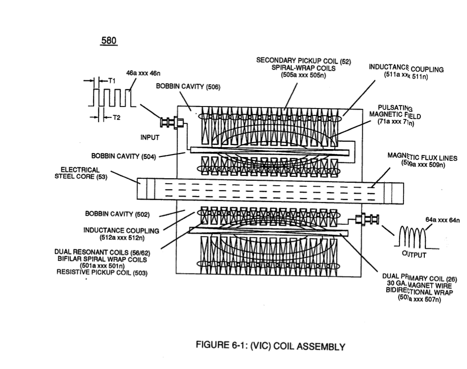
Opposite polarity Voltage Wave burst (1010) of Figure (10-5) as to Dynamic Voltage Stimulation (770B) of Figure (8-1) is simply produced when Programmable Variable Pulse-Width Pulse-Train Waveform (49a xxx 49n) is allowed to be electrically transmitted through and beyond Resonant Charging Chokes Stages (56/62a xx 56/62n + SS56/62a xxx SS56/62n) of Figure (10-4) that are not only electrically connected in sequential order but likewise magnetically linked by Inductance Coupling field (511/512a xxx 511/512n), as so pictorially illustrated in (580) of Figure (6-1).
|
Voltage Rippling Effect (1010) of Figure (10-5)
|
Dynamic Voltage Stimulation (770B) of Figure (8-1)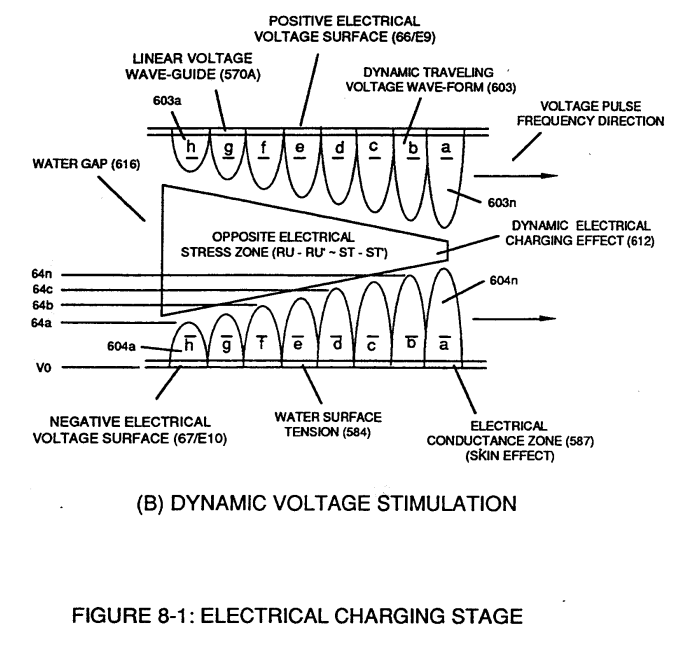 |
|
(580) of Figure (6-1)
|
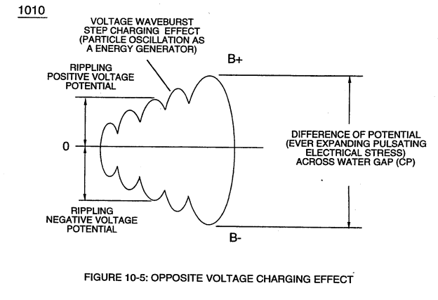
The resultant ever increasing pulsating opposite electrical voltage fields (603/604a xxx 603/604n) of Figure (8-1) having superimposed thereon counter opposing Rippling Voltage-Surfaces (64/B+a xxx 64/B-n) [Dynamic Electrical Charging Effect (612) of Figure (8-1B)], now, set ups, causes, and applies ever increasing (rubberbanding effect) Pulsating Opposite Electrical Stress (RU-RU' - ST-ST') across Water Gap (Cp)
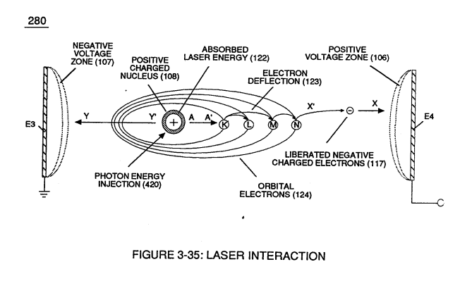
... encouraging "Particle Oscillation" as a "Energy Generator" by way of pulsating "Electrical Stress" as the combustible gas atom particles of the water molecule undergo "Particle Deflection" farthest from the point of "State of Equilibrium" and returning back to "Stable State of Equilibrium" during-pulse off-time (T2) for repeated "Snapping Action" (Rubberbanding effect) in accordance with bi-polar Voltage Rippling Effect (1010) of Figure (10-5), as so illustrated in (280) of Figure (3-35).
|
Voltage Rippling Effect (1010) of Figure (10-5)
|
(280) of Figure (3-35)
|
The greater the Electrical Stress (RU-RU' a xxx ST -ST'n) applied (64B+/64B-a xxx 64B+/64B-), the greater amount of thermal explosive energy (16/gtnta xxx 16/gtntn) of Figure (6-2) as to (70) of Figure (4-5) is released from Resonant Water Gap (Cp) (970) of Figure (10-1), as further illustrated in (70) of Figure (4-5).
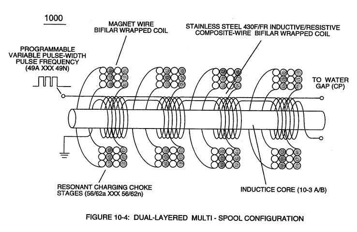 Increasing energy-yield (16/gtnt) still further (xxx 16/gtntnl+ 16/gtntn2 + 16/gtntn ... etc.) is accomplished by increasing the number of Resonant Charging Choke Stages (xxx 56/62n + 56/62n 1+ 56/62n2 + 56/62n ... etc. -S- xxx SS56/62n + SS56/62nl + SS56/62n2 + SS56/62n ... etc.) of Figure (10-4) in "Sequential Order" (-S-) since the total number of Multi-Coil Magnet bifilar coils (56/62a xxx 56/62n) serially electrically connected together are sequentially electrically linked to an equal number of serially electrically aligned Stainless Steel Resonant Coils (SS/56/62a xxx SS/56/62n)
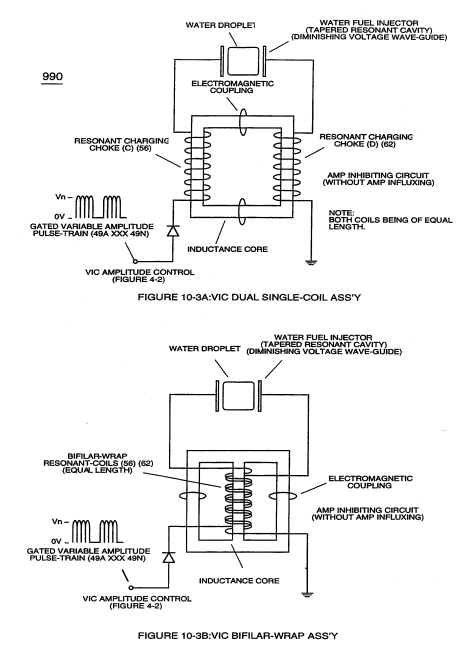
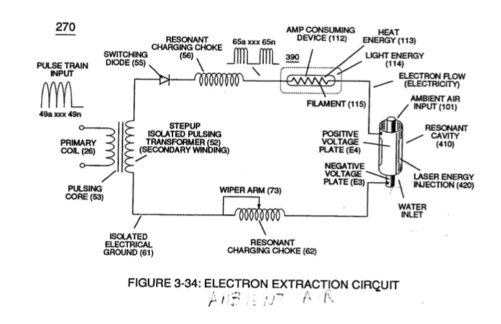
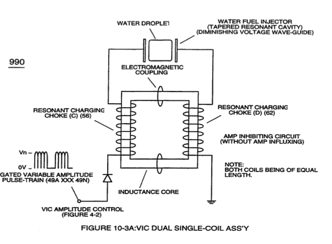
... allowing each/both bifilar coil assembly (56/62a xxx 56/62n -S- SS56/62a xxx SS56/62n) to be electrically and magnetically energized in the same progressive direction toward Water Gap (Cp) and away from blocking diode (55) of Figure (3-34) as to Figure (10-1) and Figure (10-3)
|
Figure (10-1)
|
Figure (10-3)
|
keeping amp-surge (inhibiting amp flow) to a minimal level [See Voltage Performance Graph (750) of Figure (7-14)] while enhancing Voltage Potential of Electrical Stress (64/RU-RU'a xxx 64/ST-ST'n) as additional Dual Choke Coils (56/62 _ SS56/62) are included in the stacked coil-array forming Voltage Intensifier Circuit (970) of Figure (10-1) as to (620) of figure (7-1)
|
blocking diode (55) of Figure (3-34)
|
Figure (10-3A)
|
|
Voltage Performance Graph (750) of Figure (7-14)
|
Figure (10-3B)
|
|
Voltage Intensifier Circuit (970) of Figure (10-1)
|
(620) of figure (7-1)
|
|
... see Dynamic Voltage Waveform (770) of Figure (8-1), once again.
|

In Retrospect, the use of Stainless Steel composite coil-wire (430F/FR) consists of both inductance and resistive properties (typically .0048 ohms per foot) which when combined together in metallurgical form aids amp restriction beyond the singularly use of self-inductance magnet (Copper) coil-wire having a lower resistive value.
Stainless Steel bifilar Coil-Stage Assembly (SS56/62a xxx SS56/62n) is electrically placed between Magnet Coil-Stage Assembly (56/62a xxx 56/62n) and Water Gap (Cp) to obtain optimum Voltage to Amp Differential Ratio (Vhighest:Alowest ratio).
Together, Coil Stages (56/62a xxx 56/62n + SS56/62a xxx SS56/62) added/stacked sequentially into a single overall coil-array assembly (990A/B) of Figure (10-3) forms Amp Inhibiting Network (Figure 8XA) as to (970) of Figure (10-1) (hereinafter called VIC Multi-Coil Spool Assembly).
The magnet Coil-Wire (56/62) is best suited for Voltage inducement while the inductance/capacitance/resistance properties of Stainless Steel coil-wire (SS56-SS62) is appropriately used to restrict electron movement beyond the self-inductance of each energized coil when elevated voltage levels (up to beyond 40 kilovolts) are to be reached/obtained without experiencing any appreciable amount of "Amp Influxing."
Generally, magnet coil-wire length is longer than the Stainless steel coil-wire length and magnet bifilar-coil (56/62) is placed on top of Stainless Steel bifilar-coil (SS56/62) to maximize mutual inductance coil-field (Rp2) (adding Rp1+Rp2) of (690) of Figure (7-8) to cause coil capacitance (Cda xxx Cdn) to help maintain and even increase pulse voltage amplitude (xxx Vn + Vn 1 + Vn2 + Vn .... etc.) while the resistive value (Rs2) of SS Coil-Wire (SS56/62) performs the work of further resisting the flow of amps not inhibited by both self-Inductance fields (Rpl + Rp2), as so illustrated in (690) of Figure (7-8).
|
(690) of Figure (7-8)
|
In all cases, bifilar coils (56/62 - SS56/62) are electromagnetically orientated in the same direction.
In terms of operability, electrically flexing (Particle Oscillation) the combustible atoms of the water molecule as a "Energy Generator" by way of opposite voltage polarity is extremely economical since voltage is not consumed in an electronic circuit.
 Amp Inhibiting Circuit (970) of Figure (10-1) restricts/inhibits amp flow to a minimal level while elevating "Difference of Potential" to the highest possible level.
The greater the "Difference of Potential" (in this case, electrical stress) the greater amount of work is performed
... thereby, being in compliance with the Laws of Physics since atoms are the source of all energy in our physical universe and atoms are directly responsive to / stimulated by external electrical forces.